Anybody have experience with Panasonic ECO caps? NOS 15,000uf@50V are available for just 2.9$/pc. Have never use them before, are they good?
Panasonic makes good CAPs. If they real#1: If they are not 20 years old, but some times 20+ years are still good. I have tested NOS CAPs just approaching 40 year mark and still test what the ratting says. Slowly charge them up hold over night. cycle many times retest then use.
On the other hand I been sold counterfeits that looked good but were way off on the uF rating and tested poor ESR.
On my job as A HVAC tech I pulled old Panasonic CAPs out of VFD drive motors that I installed 5 to 10 years ago when the equipment was being replaced. I strip them of the circuit board test them and still good after being used 24/7/367 and use them in my projects.
CAP tester ( DE-5000 Handheld LCR Meter ) DE-5000 Handheld LCR Meter - Multi Testers - Amazon.com
this is what I use to test CAPs with. it used to be almost $300 before now it been replaced with a new model DE-6000 so the old one price drop is a killer deal. this is what I used to teach myself more about capacitors.
YouTube
YouTube
here are some Youtube about CAPs and the test meter
Last edited:
ThermalAlchemy, thank you for sharing your experience! I already ordered set of 8, as soon as they arrive will slow charging cycles, as you suggest.
for those who would like to buy this caps here is source:
**NEW**Panasonic Electrolytic Filter Capacitor 15000uf 50v 85 degree Celcius | eBay
for the price 2.89$/pc its bargain!
for those who would like to buy this caps here is source:
**NEW**Panasonic Electrolytic Filter Capacitor 15000uf 50v 85 degree Celcius | eBay
for the price 2.89$/pc its bargain!
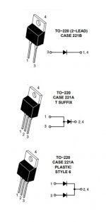
Hi, I am building a PS for an F5T and wanted to double check that I should be cutting off the middle terminal as shown in the closeup shot of the diode screwed to the heatsink. Also, is there a difference or benefit to using this style of rectifier vs a pair of diode bridges?
Thanks,
John, noob
Thanks,
John, noob
There are single and dual diodes.
In case of single diode: (1) in some models middle pin is factory cut; (2) you don't have to cut middle terminal. pins 1 & 3 on the board acc. to schematic are in parallel connection
In case of dual rectifier (3) - don't cut pins, use all 3 holes on PCB - diodes will be paralleled
6V6, correct me if I'm wrong
Those through hole rectifiers are mostly fast recovery (Schottky), monolithic bridges - slow. Both will work fine; some prefer fast recovery, some slow.
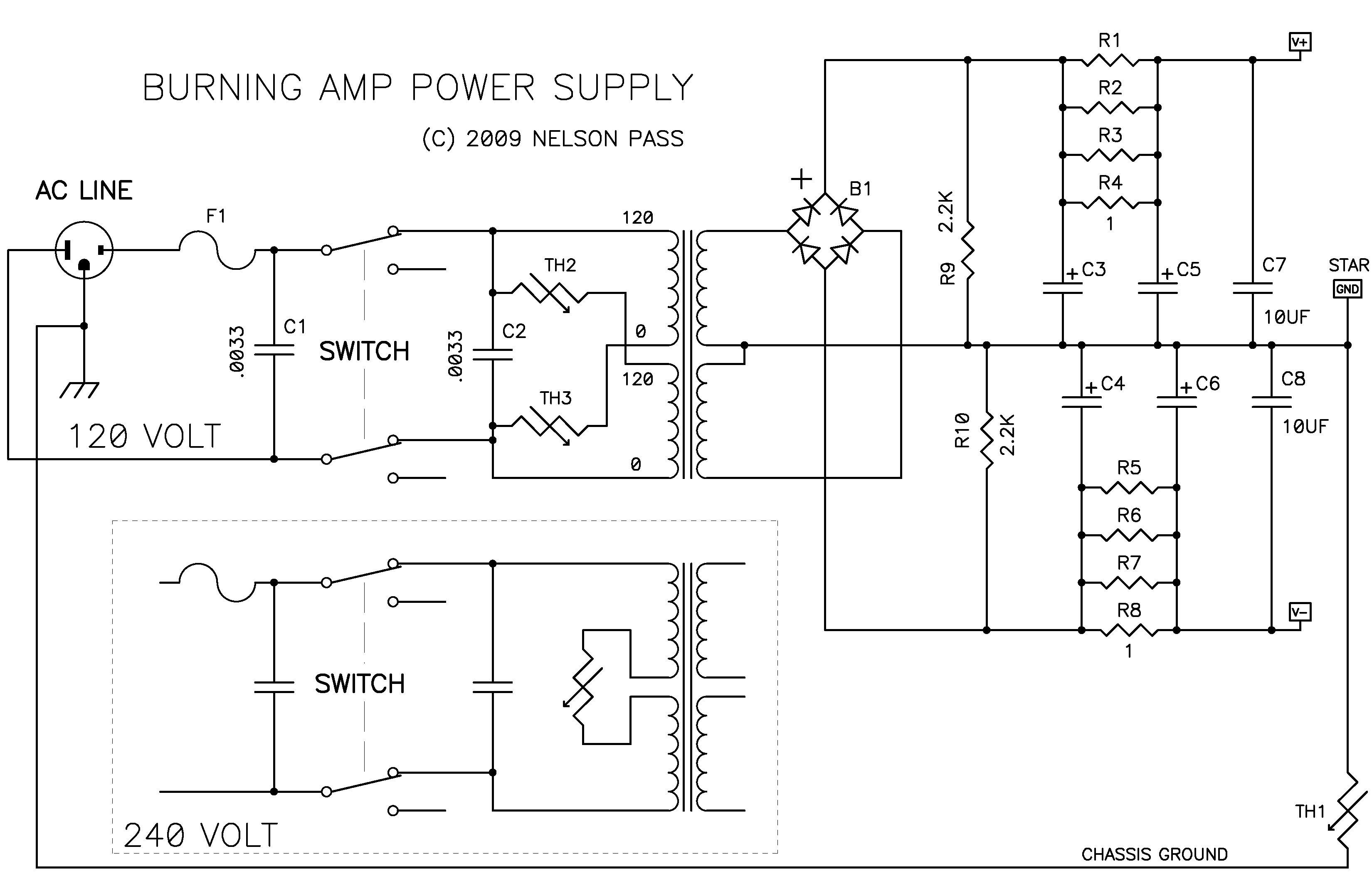
Nelson prefers slow recovery diodes:
In case of single diode: (1) in some models middle pin is factory cut; (2) you don't have to cut middle terminal. pins 1 & 3 on the board acc. to schematic are in parallel connection
In case of dual rectifier (3) - don't cut pins, use all 3 holes on PCB - diodes will be paralleled
6V6, correct me if I'm wrong
Those through hole rectifiers are mostly fast recovery (Schottky), monolithic bridges - slow. Both will work fine; some prefer fast recovery, some slow.
Nelson prefers slow recovery diodes:
Rectifiers
Yeah, sure, rectifiers are important, after all, the AC has to get converted to DC, but I don't like the fast recovery types that some audiophiles have raved about. Fast recovery means that they withstand many amps and volts in a tenth of a few nano-seconds, something we don't see very often on the old 60 Hz AC line. They are essential element in switching power supplies, but for regular "linear" power supplies, I much prefer SLOW diodes, and we create them by placing small capacitor circuits across the diodes, which greatly reduces radiated noise.
Attachments
Sorry if this has been asked before.
I’m building a 240v version. Antek AS-3222 transformer.
What values of thermistor and capacitor do I require on the primaries
Many thanks.
Andrew
I’m building a 240v version. Antek AS-3222 transformer.
What values of thermistor and capacitor do I require on the primaries
Many thanks.
Andrew
Assistance with transformer
I have got a bit confused with how to connect the transformer to the PSU board. My transformer is 240v. Sec 1 22v Red-Yellow, and Sec 2 22v Blue and grey. I have populated the PSU with the 8 x diodes and heatsinks and just not sure how I connect the secondaries to the diode board.
I have got a bit confused with how to connect the transformer to the PSU board. My transformer is 240v. Sec 1 22v Red-Yellow, and Sec 2 22v Blue and grey. I have populated the PSU with the 8 x diodes and heatsinks and just not sure how I connect the secondaries to the diode board.
Sorry if this has been asked before.
I’m building a 240v version. Antek AS-3222 transformer.
What values of thermistor and capacitor do I require on the primaries
Many thanks.
Andrew
I use 2 CL-60 in series for my F5T. Serves me well so far. Not sure what amp you are building so I can't advise you on the capacitor values needed.
I have got a bit confused with how to connect the transformer to the PSU board. My transformer is 240v. Sec 1 22v Red-Yellow, and Sec 2 22v Blue and grey. I have populated the PSU with the 8 x diodes and heatsinks and just not sure how I connect the secondaries to the diode board.
One set should go to the AC1A and AC1B, and the other to AC2A and AC2B.
Thanks for the reply
Just to clarify, I have 4 secondary wires, 1 to AC1a, 2 to AC2a and so on.
Thanks
Andrew
Just to clarify, I have 4 secondary wires, 1 to AC1a, 2 to AC2a and so on.
Thanks
Andrew
3300pF X/Y rated and CL-60. It doesn't change.
Place CL-60 in series between the two primaries, as shown in Firstwatt schematic.
Place CL-60 in series between the two primaries, as shown in Firstwatt schematic.
Last edited:
CL-70 is rated for 4 amps, whereas CL-60 is 5A. This will be fine in 240v mains. It will run quite hot, as they all do, so make sure there's some ventilation around it.
hello
I have 3 questions for the construction of the power supply for the M2-X
*** must C1 and C2 be put on the primary 230V because I saw schema with only C2
*** the primary of my transformer has only 1 winding. Must put the CL60 thermistor at the transformer input
*** what is the diameter of the connection cables between transformer / diode bridge / psu card
Thank you in advance.
hello
I have 3 questions for the construction of the power supply for the M2-X
*** On the schema burning amp 2009 #712 there are C1 and C2 on the 230v. and 3 filter capacitors. Whereas in the 2005 #236 power supply scheme there is only one capacitor on the 230v, and 4 filter capacitors.
Quel schema dois je prendre pour le M2?
*** the primary of my transformer has only 1 winding. Must put the CL60 thermistor at the transformer input?
*** what is the diameter (or section) of the connection cables between transformer / diode bridge / psu card
and psu card/cinch rca
Thank you in advance.
Last edited:
C1/C2 - Use both or just C2. Remember this must be X2/Y2 rated for across the mains.
Use one CL-60 in series with the live lead on the primary.
Similar thickness to the wire on the transformer itself.
Use one CL-60 in series with the live lead on the primary.
Similar thickness to the wire on the transformer itself.
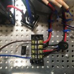

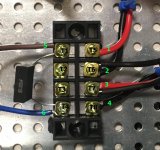
The wiring doesn't look right when compared to:
An illustrated guide to building an F5
Someone please correct me if I'm wrong as I'm no expert but:
Your center terminals aren't connected to any AC input. You end up with red from one coil connected and black from another terminal connected.
It should go left to right: black from one winding, black from the other winding, red from the winding that matches the first black wire then red from the winding that matches the second black wire.
Then the A/C input should be at the center with 2 thermistors, one going from each center terminal to an the terminal to the outside of it.
the AC will be connected to the center 2 posts, which is across the cap. (AC in will connect to the same terminals as the blue capacitor)
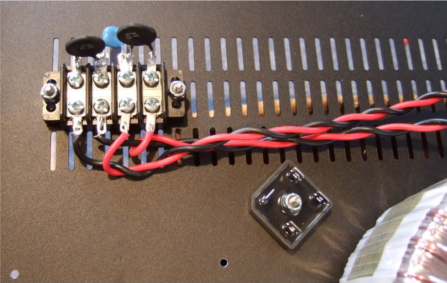
It takes a bit to trace where everything is going but the AC comes in on the two center terminals at the top. That connects one side of the AC mains to each input of the transformer directly. It then feeds the other side of each input through a thermistor.
Since the wires to the windings skip over each other on their way to the terminals one st of wires the red wire gets wired direct to the power input and the other set of wires gets the black wire fed directly. Then both windings get their other color fed from a thermistor connected to the input.
In the attached picture:
Move wire #5 to T2
Wire #6 to T3
move the capacitor to T2 and T3 as well
Move wire #2 to T7
wire #3 to T6
move the thermistor to T5 and T6 and add another one between T7 and T8
An illustrated guide to building an F5
Someone please correct me if I'm wrong as I'm no expert but:
Your center terminals aren't connected to any AC input. You end up with red from one coil connected and black from another terminal connected.
It should go left to right: black from one winding, black from the other winding, red from the winding that matches the first black wire then red from the winding that matches the second black wire.
Then the A/C input should be at the center with 2 thermistors, one going from each center terminal to an the terminal to the outside of it.
the AC will be connected to the center 2 posts, which is across the cap. (AC in will connect to the same terminals as the blue capacitor)
It takes a bit to trace where everything is going but the AC comes in on the two center terminals at the top. That connects one side of the AC mains to each input of the transformer directly. It then feeds the other side of each input through a thermistor.
Since the wires to the windings skip over each other on their way to the terminals one st of wires the red wire gets wired direct to the power input and the other set of wires gets the black wire fed directly. Then both windings get their other color fed from a thermistor connected to the input.
In the attached picture:
Move wire #5 to T2
Wire #6 to T3
move the capacitor to T2 and T3 as well
Move wire #2 to T7
wire #3 to T6
move the thermistor to T5 and T6 and add another one between T7 and T8
Attachments
Last edited:
- Home
- Amplifiers
- Power Supplies
- diyAudio Power Supply Circuit Board v3 illustrated build guide