Actually, I would still like to know how, when and why one would decide to add (or omit) the R_Optional1-6 (optional resistors).
Also, I am very interested in all decisions RE:
Best to all
-Ses
Also, I am very interested in all decisions RE:
- R11-R12 (output snubber resistors)
- RS1-RS2 (input snubber resistors)
- CX1-CX2 (input snubber capacitor)
- CS1-CS2 (input snubber capacitor)
Best to all
-Ses
If you read posts #43 through #57, your questions should be answered regarding snubbers and RC filters. No need to populate optional resistors or snubbers if used with M2x.
Is it OK to use this PSU in an M2x build with the standard components in the BOM I plan to use 2x bridge rectifiers. Toroid is 2x 18V 10A. This one https://www.ebay.com.au/itm/NORATEL...e=STRK:MEBIDX:IT&_trksid=p2060353.m1438.l2649
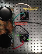
I have read and re-read this (entire) forum, but cannot definitively tell exactly how to connect the 18V AC leads from my transformer to the PSUv3 board using the diode rectifier bridge. I've posted a photo of my current build below -- and indicted what I *think* I understand about how this should be connected to the 18V AC input. I know this is a trivial question and one I should be able to figure out (or infer) but I simply don't feel confident that I'm understanding this correctly. Thank you in advance!
Hi,
Did you get any answer on this issue? I have the same problem :-((.
thanks
Regards
Is this correct
Testing the PSU and I am getting 64 VDC reading. The transformer is 2 x 22V, and I have wired it as 1st set of secondaries to AC1A and AC1B. The second set of secondaries wired to AC2A and AC2B. I wanted 30-32 VDC for the Pearl 2. What have I done wrong.
Andrew
Testing the PSU and I am getting 64 VDC reading. The transformer is 2 x 22V, and I have wired it as 1st set of secondaries to AC1A and AC1B. The second set of secondaries wired to AC2A and AC2B. I wanted 30-32 VDC for the Pearl 2. What have I done wrong.
Andrew
Australia is 230V so the transformer primaries should be wired in series. Did you wire them in parallel? Parallel would double the secondary voltage.
I only have 2 wires n the primary side.
Just to confirm, when I measure V+ and Grd= 32V, and V- and Grd =32V
If I measure V+ and V- it is 64V
Just to confirm, when I measure V+ and Grd= 32V, and V- and Grd =32V
If I measure V+ and V- it is 64V
I only have 2 wires n the primary side.
Just to confirm, when I measure V+ and Grd= 32V, and V- and Grd =32V
If I measure V+ and V- it is 64V
Specifications on the transformer, or accompanying documentation?
If available, please share.
Then your supply is working properly. It is a bipolar supply with positive and negative supply voltages, which is required by the Pearl 2:
Building a Pearl 2
Building a Pearl 2
Good evening,
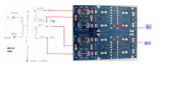
I'm building an F6 , I have a 400VA ,230 V transformer and I would like to be sure if the connections presented in the attached picture (transformer to PSU board) are done right. Also if the 2 LEDs are installed with the right orientation.
Thank you
Regards
I'm building an F6 , I have a 400VA ,230 V transformer and I would like to be sure if the connections presented in the attached picture (transformer to PSU board) are done right. Also if the 2 LEDs are installed with the right orientation.
Thank you
Regards
Attachments
Last edited:
25A 200V, or 35A 200V
going to 400V does no harm.
Hi,
Thanks for the posts... I am building the M2X Amp using the PSUv3 from the store. I need to purchase parts for the final case assembly. Looking at
AS-3218 - 300VA 18V Transformer - AnTek Products Corp and wondering if it is ok to go to 'higher' rated diodes and get, "50A 1000V KBPC Single Phase, Full Wave 50 Amp 1000 Volt Electronic Silicon Diodes"
(Pack of 2 Pieces) Chanzon KBPC5010 Bridge Rectifier Diode 50A 1000V KBPC Single Phase, Full Wave 50 Amp 1000 Volt Electronic Silicon Diodes: Amazon.com: Industrial & Scientific
Also would love some help in a particular part number for the case switch and protector fuse? If it helps, I am going to use the 4U deluxe chassis from the diyaudio store.
That bridge rectifier should work just fine. Here's a link to the Schurter power entry module that fits the case:
4304.6090 Schurter | Mouser
Note that this is supplied if you purchase the rear panel kit from the diyAudio store. Recommended.
4304.6090 Schurter | Mouser
Note that this is supplied if you purchase the rear panel kit from the diyAudio store. Recommended.
I'd second WKCox's reply.
(I'm afraid you won't get a reply from AndrewT as he's gone to listen to the great big stereo in the sky.)
(I'm afraid you won't get a reply from AndrewT as he's gone to listen to the great big stereo in the sky.)
Building a PS v3 with an Antek AS-4218 to go in a 5U chassis.
Read that optional 0.47R-3W resistors 1 thru 6 can be added for high current power requirements.
Projected uses are for an Aleph J, then perhaps an M2x or ZM SissySIT.
Seek counsel as to whether it is advisable for me to include some, or all, of the optional resistors.
I have them on hand.
Read that optional 0.47R-3W resistors 1 thru 6 can be added for high current power requirements.
Projected uses are for an Aleph J, then perhaps an M2x or ZM SissySIT.
Seek counsel as to whether it is advisable for me to include some, or all, of the optional resistors.
I have them on hand.
- Home
- Amplifiers
- Power Supplies
- diyAudio Power Supply Circuit Board v3 illustrated build guide