That is fine, I would suggest keeping one type of cap on each side of the resistors. Also, place the higher voltage caps closer to the diodes.
That is fine, I would suggest keeping one type of cap on each side of the resistors. Also, place the higher voltage caps closer to the diodes.
Great. It would be a shame to waste them. What about using as high values as 80 000uf caps? The BOM suggests 10 000-15 000 uf caps. I will be using them for F4 and F5.
Star Ground ?
Hi Folks ,
I have sound from both channels ,but a good hum to match . I haven't connected the star ground yet . I have a cable prepped complete with in CL60 .
From what I understand …. this goes from the G on the psu to the chassis ?
Thank you , Richard
Hi Folks ,
I have sound from both channels ,but a good hum to match . I haven't connected the star ground yet . I have a cable prepped complete with in CL60 .
From what I understand …. this goes from the G on the psu to the chassis ?
Thank you , Richard
"star ground", what do you mean?
The amplifier must have a Main Audio Ground.
It's where the Signal Input, Signal Output and Power all receive a common reference from.
If you don't have this wired up the audio just won't work !
Or
did you mean Protective Earth?
This makes mains equipment safer to operate.
This is what will blow the Mains fuse if there is a catastrophic mains failure inside the Chassis, that shorts to Neutral or to Chassis.
This does not stop the audio working. This does not cause hum.
Or
Did you mean A connection from Chassis to main Audio Ground?
This is what stops exposed terminals becoming Live during a catastrophic mains failure.
This too blows the mains fuse.
This does not stop the audio working. This does not cause hum.
If you have audio and hum, then that is due to a wiring error. Not to a missing Chassis connection.
I have audio and hum ….. I have no star-ground connected to the chassis .
I have loud hum on both channels ….. ?
I have to go out for a couple of hours ,but will check back later .
Cheers ,Richard
I have loud hum on both channels ….. ?
I have to go out for a couple of hours ,but will check back later .
Cheers ,Richard
No connection to Chassis will not stop the amp working.
No connection to Chassis will not cause hum.
Your hum is coming from a wiring error.
No connection to Chassis will not cause hum.
Your hum is coming from a wiring error.
Ok …. found the source of the darn hum ….. XLR cable . Duh 🙄
Now I just need to set the DC off set …. I have -9.8 and -28.7 …. I'm lust watching it as the temp goes up !
From what I've read , I need 100mv using multi-turn at R8 measured across the speaker output .
Have I understood this procedure correctly ?
Thank you , Richard
Now I just need to set the DC off set …. I have -9.8 and -28.7 …. I'm lust watching it as the temp goes up !
From what I've read , I need 100mv using multi-turn at R8 measured across the speaker output .
Have I understood this procedure correctly ?
Thank you , Richard
Attachments
This does not sound right...................... From what I've read , I need 100mv using multi-turn at R8 measured across the speaker output .
Have I understood this procedure correctly ?
..............
Where is R8?
Where is 100mV AC or DC measured?
This does not sound right.
Where is R8?
Where is 100mV AC or DC measured?
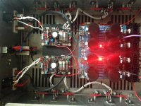
mV DC measured at the speaker terminal . R8 is the up-right multi-turn closest to the rear of the PCB .
Chip amp … Marra.
I also have one side hotter than the other ?
Cheers .
I also have one side hotter than the other ?
Cheers .
Attachments
Last edited:
There seems to be many versions of the schematic here …. all pretty generic and rather confusing for me with little or no knowledge . I think I've done pretty good to get this far .
That's not a chip amp. It's a class A amp. Sounds like you're confusing DC offset with bias adjustment. DC offset should be as close to zero as possible when the amp is warmed up. Normally you measure your bias current at an emitter/source resistor. The grounding scheme in that schematic looks dangerous.
Hi J ,
I have ignored the grounding suggested on the schematic …. As you pointed out …. I'm pretty confused about the bias/ offset thing .
BTW, the boards are Aleph boards from Chip amp .
Rich
I have ignored the grounding suggested on the schematic …. As you pointed out …. I'm pretty confused about the bias/ offset thing .
BTW, the boards are Aleph boards from Chip amp .
Rich
Chip amp normally refers to an amp in an integrated circuit. To set your bias you need to measure the voltage drop across your source resistors. If you used .47 ohm resistors for R118, 120 & 122 you should measure 235 mv across them. Measure across all three one at a time and average the result. After that is set, check your DC offset at the speaker output and adjust it as close to zero as you can. Normally your bias adjustment is what determines how hot your heat sink will be. The more bias current you have, the hotter your heat sink will be.
- Home
- Amplifiers
- Power Supplies
- diyAudio Power Supply Circuit Board v3 illustrated build guide