I have the ground from the AC inlet direct to the chassis . I also had the amp board grounded to the psu board then to the chassis via CL60 . The fuse blew and the CL60 smoked …. Something is not quite right 🙂
Hmmm.... Photos please.
Does the CL60 insulate as in the requirement here on the schematic ?
Note the CL60 on the earth from the IEC ????
Note the CL60 on the earth from the IEC ????
Attachments
Last edited:
Note the CL60 on the earth from the IEC ????
Wow... That's a genuinely bad idea... Don't do that.
Earth ground should connect directly to the case. You have a short to ground somewhere. Get your ohm meter going and find it before plugging into mains again. That CL60 in the ground circuit is actually dangerous.
Its showing TH CL60 on the schematic ….. ?
I don't know why they've done that but Earth ground should be connected directly to the metal case of the amplifier. If there is a short circuit to ground in the amplifier it's that ground connection then trips your breaker or blows your fuse and stops the short from killing you. Putting something in series with that ground may prevent the breaker/fuse from interrupting your mains feed. If that CL60 burned up you have a short to earth ground in the amp that should have blown the fuse/breaker. You need to find it before you apply power again for your own safety.
I have a short from - rail to ground ….. Cant find it ?
Sounds more like mains to earth ground. Your amplifier case was going live.
My PSU checks out ok …..no fuses blowing … I have 2A in line . No problems until I wired the amp boards in
For the CL60 in the earth ground circuit to burn up there had to be current flowing through it. If there are no shorts to ground there won't be any current flow in the earth ground circuit. Look for a loose strand of wire or anything that may have touched chassis ground. Look for a small burn mark in your chassis. You may have had a strand of wire touch the chassis and burn up. Post some good pictures. One of the Hawk eye's around here will likely see it. This is likely on the mains side of the transformer. or in the transformer itself.
This tells me you did not use a bulb tester to power up the transformer.................. I also had the amp board grounded to the psu board then to the chassis via CL60 . The fuse blew and the CL60 smoked …. Something is not quite right 🙂
Then I mis-understood …. I thought I'd read NOT to use the tester once the amp -boards are wired up ?
Perhaps a step by step would help me … ?
Rich
Perhaps a step by step would help me … ?
Rich
Unscrew the PSU board from the standoffs, place a piece of cardboard under it, power it up and see if the problem persists.
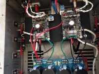
There's a short to the chassis here. Unplug the amp and start probing with an OHM Meter before you electrocute yourself.
There seemed to be a problem with the 2.2K resistor . On one channel I got continuity from both sides to ground . I stripped the whole thing out and re-wired everything back to the IEC .
I couldn't see anywhere that had burn marks .
I pulled them and ordered some more from a different supplier .
I'm working tomorrow so no messing with this thing ….. back at it Friday
thank you for your help ,Richard
I couldn't see anywhere that had burn marks .
I pulled them and ordered some more from a different supplier .
I'm working tomorrow so no messing with this thing ….. back at it Friday
thank you for your help ,Richard
I don't know how everyone else does it but when I assemble an electrical device, I check for continuity to chassis on every module as I install them, before ground connections are made.It always looks like there will be no problem and loads of clearance to chassis parts but all it takes is a strand of wire to become dangerous. I also check between rails and outputs on amplifier boards or any high power transistor board with the meter set to diode check. Red lead on V+ rail, black on output, the red on output, black on - rail. If you have a voltage reading on either rail you likely have an output device or driver shorted or reversed. After the unit is assembled, check for continuity between mains, neutral and chassis. If you see any sign of trouble, find it before you power up. The problem won't fix itself. There should never be that surprise flash and smoke when you power up the first time. Continuity checks only take a couple minutes and can save lots of parts and/or your life. Really the only surprise you should run into is possible meltdown from oscillation, but that's what your bulb limiter is there for.
Fets ?
PSU is perfect …… now it turns out I need to replace all the actives . Not really upset about it . It makes sense to have a clean bill of health for the entire amplifier .
Who has matched fets ….. any ideas please ?
Thank you ,Richard
PSU is perfect …… now it turns out I need to replace all the actives . Not really upset about it . It makes sense to have a clean bill of health for the entire amplifier .
Who has matched fets ….. any ideas please ?
Thank you ,Richard
- Home
- Amplifiers
- Power Supplies
- diyAudio Power Supply Circuit Board v3 illustrated build guide