PCB layout question
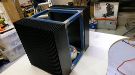
I have a pair of the PCB’s and have custom mounted them on nice big heat sinks. The two are on opposite sides of the chassis I made
Here is the question/ dilemma :
If the PCB’s are oriented so the power transistors are at the top of their heat sink, the two PCB’s arefacing in opposite directions. IE: the inputs,etc. are not at the same end to make wiring symetrical.
Any ideas?
For proper cooling the transistors shouldn't be mounted at the top of the heatsink. They should be mounted slightly below center. If that's not possible move them lower, not up.
With a layout such as the Honeybadger it's impossible to have symetrical wiring. This isn't a huge problem, just do some careful planning to keep wiring short and be careful with signal wire routing.
With a layout such as the Honeybadger it's impossible to have symetrical wiring. This isn't a huge problem, just do some careful planning to keep wiring short and be careful with signal wire routing.
A noise I can't seem to fix
Hello everyone, I'm trying to build a honey badger mono block.
I've got it running perfectly bias wise and have made it output 150wrms at 8ohm and it sounds good music wise.
However I have a base line hash noise which is always there and does not change with signal input versus output.
I've traced the noise from the output, through the bias and front end power control section and into the collector of the main input transistor.
Then up through the whole gain circuit to the output.
The input itself is dead quite and the power rails are noise free also.
I've tried replacing all the transistors completely with no change to the noise.
I've built it using the suggested parts list from digikey.
It looks to me like a big loop oscillation.
But I'm not very experienced and need help.
The noise is very audible on my 101db speakers
Attachments
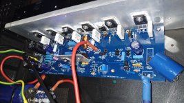
Start by replacing the input cap with something that fits the board and fix up your wiring. Power and return wiring needs to run parallel or twisted together to cancel noise emissions from each other. That goes for power supply and output wiring. There's been some debate lately but normally it's preferred to run the speaker return wire back to the power supply ground point. An input cap hanging off the board like that is a great antenna to pick up all those noise emissions.Hello everyone, I'm trying to build a honey badger mono block.
I've got it running perfectly bias wise and have made it output 150wrms at 8ohm and it sounds good music wise.
However I have a base line hash noise which is always there and does not change with signal input versus output.
I've traced the noise from the output, through the bias and front end power control section and into the collector of the main input transistor.
Then up through the whole gain circuit to the output.
The input itself is dead quite and the power rails are noise free also.
I've tried replacing all the transistors completely with no change to the noise.
I've built it using the suggested parts list from digikey.
It looks to me like a big loop oscillation.
But I'm not very experienced and need help.
The noise is very audible on my 101db speakers
Hi Gareth,
I have to agree with Jeff. Once you have that done it should settle down. It is a stable design.
As for the "magic" parts that are oversized (your input capacitor), there are better options when you consider lower voltage parts, keeping the value to what is in the schematic. Select one of those capacitors that will fit in the board. The dielectric is more important than the name printed on the part. Try Polypropylene or similar.
-Chris
Testing the badger. When I turn r30 to adjust bias and gets in the area of 15 ro 20mv it will suddenly jump to +/-60mv and my dim bulb protector will light dimly any thoughts? When I reverse r30 turns it slowly goes down then jumps to +/- 5mv
If the amp is testing normal before adjusting bias current, remove the bulb limiter. bias current can't be properly adjusted with any sort of current limiter in series with the supply.
Stick a 'scope on the output when you are adjusting the bias. It could be oscillating.
-Chris
-Chris
Same noise unchanged
Thank you Jeff for your observations.
I'd not cleaned up my wiring properly since I've pulled out the board for diagnosis so many times.
I've tried many things wiring wise for the power supply and nothing has changed the noise on the output.
I used long wires and power the board far away from the box using all different power supply combinations.
I've changed around all of the components including the rectifier.
My power feed into the amp is steady.
I don't know why you are against purpose built capacitors for the input.
It's just a cheap jantzen poly cap that is recommended for this use. And is approximately the correct size.
As I said before my input is completely noise free.
To further test this I now have no cap installed at all.
I've also twisted the power cables.
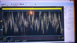
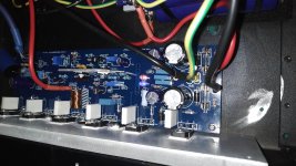
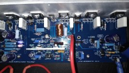
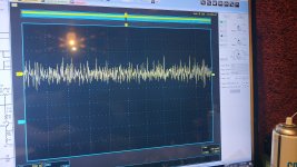
Here are photos of the same noise like this.
First photo is of the output noise.
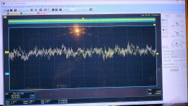
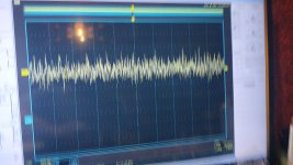
Second is of the base of the input transistor.
Third is of the main positive rail at 100mv sensitivity, looks to be a normal tiny bit of left over ripple.
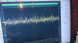
Forth is of the input transistor collector.
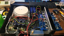
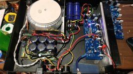
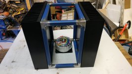
Number five is of the amp as it is now.
I can see the noise loop from the output through the control circuit and back into the input transistor. Then up the whole gain circuit again in a big loop.
This is not my first amp. But I've never had this issue before.
I appreciate your help.
Have I made a mistake on the board?
Are there tests I can do to locate the start of the noise/oscillation
Thank you Jeff for your observations.
I'd not cleaned up my wiring properly since I've pulled out the board for diagnosis so many times.
I've tried many things wiring wise for the power supply and nothing has changed the noise on the output.
I used long wires and power the board far away from the box using all different power supply combinations.
I've changed around all of the components including the rectifier.
My power feed into the amp is steady.
I don't know why you are against purpose built capacitors for the input.
It's just a cheap jantzen poly cap that is recommended for this use. And is approximately the correct size.
As I said before my input is completely noise free.
To further test this I now have no cap installed at all.
I've also twisted the power cables.
Here are photos of the same noise like this.
First photo is of the output noise.
Second is of the base of the input transistor.
Third is of the main positive rail at 100mv sensitivity, looks to be a normal tiny bit of left over ripple.
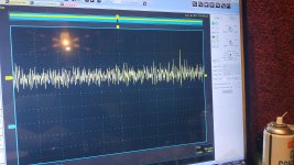
Forth is of the input transistor collector.
Number five is of the amp as it is now.
I can see the noise loop from the output through the control circuit and back into the input transistor. Then up the whole gain circuit again in a big loop.
This is not my first amp. But I've never had this issue before.
I appreciate your help.
Have I made a mistake on the board?
Are there tests I can do to locate the start of the noise/oscillation
Attachments
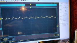
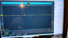
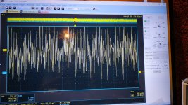
Same noise on both sides of trim pot R30 regardless of position
I have tested the noise at the leg of R39 and R29.
No change to the noise at all weather it's 500ohm or normal bias.
First two are at normal bias.
Second two are at minimum bias.
Oscilloscope set to 1v
I have tested the noise at the leg of R39 and R29.
No change to the noise at all weather it's 500ohm or normal bias.
First two are at normal bias.
Second two are at minimum bias.
Oscilloscope set to 1v
Attachments
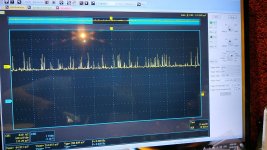
An obvious basic test is to simply remove the input cap and thus prevent any signal input at all from getting to the amplifier via the normal path. If the noise persists, you have a strong or local source of EMR that is reaching the input stage either directly or via any long, unshielded or un-bypasssed leads making connection to the amplifier, including PSU, speaker or any other gizmo you have connected for any reason, including the scope hardware itself.
A test - Try clipping your probe and ground clip to a 1M resistor and have a look at the waveform as it is. Is there any similarity to the noise pattern? Wave it about and see where the noise looks strongest (take care not to go near the power though - could be nasty).
Look at the periodicity of the scope waveforms, particularly at the input transistor base on higher res, if possible. To me, the collector noise looks like a large scale version of that at the base, as we might expect. The waveform also seems like it has variable interval bursts with a repeated steady amplitude pattern, similar to simple switching power supplies or digital control code. You may have a Toroidal transformer but what about your environment? such as the neighbour's solar power array, faulty CFL, LED or standard fluorecent lighting, laptop PSU, TV etc?
So, If you can't make any difference to the noise by messing with the amplifier, you will probably find something by checking out external sources to your test system that you haven't considered yet. Look around.
As you are using Arta software, I assume your PC powers the soundcard too, so it could well be putting a lot of dirt into the measuring system at the same time. At least I know that I can't properly use any of my PCs for audio or soundcard test uses unless there is an optical or similarly isolated digital link to an external ADC or DAC to reduce the grunge from the noisy PC ground. PC chassis ground BTW, is always a very noisy source and it's common to audio signal ground - not much you can do about that and it's why I ditched the PC soundcard approach and eventually bought a 'scope. Scope software now drives a PC's monitor via USB, so you can still have the full sized display, if you wish.
Edit: You attached more screens since I began my post GL, I'll have to look again.
Last edited:
NOW PLAYING MUSIC. I would like to thank the authors and members for all the help without you I could not be enjoying this great hobby. I did notice that my led’s red and blue got turned around so that on one side blue is - and the other blue is+. oddly the V+ Side is always brighter regardless of color. Is this normal?
oddly the V+ Side is always brighter regardless of color. Is this normal?
I think so. My Badger is the same. Probably the different LED types have different brightness.
R51 controls current through the LED on the positive rail and R52 controls it on the negative rail. R51 is 22k and R52 is 100k so current flow through the LEDs will be a lot different between rails.
NOW PLAYING MUSIC. I would like to thank the authors and members for all the help without you I could not be enjoying this great hobby. I did notice that my led’s red and blue got turned around so that on one side blue is - and the other blue is+. oddly the V+ Side is always brighter regardless of color. Is this normal?
Yes that is normal, the two colours use different voltages.
But also blue is much more receptive to the human eye and always appears brighter than red does with the same lumen output.
That being said the positive side uses a 22k power resistor and the negative side uses a 100k power resistor for the LEDs.
So they will be different outputs.
I assumed it was to even out the different voltage needs. Red is about a volt less than blue from memory.
If in doubt check your power voltages.
They should be exactly the same.
Large input capacitors
Hi Gareth,
Anyway, that isn't the issue with the capacitor you used. The issue is it's size. It is large and does not fit on the board. Consider the foil of the capacitor as an antenna. The input circuit is a high impedance point, so any noise picked up will stay mostly in the circuit instead of being shunted to ground. Large capacitors are generally avoided when you have circuit conditions like this. Your only saving grace here would be the low (hopefully) output impedance from your source.
You wouldn't create a flag of metal and connect it to your input circuit, but that is essentially what you have done by using a huge capacitor. There are a few sensitive areas in amplifiers where you do not want random noise pick-up and this would be one of them. Unfortunately, the noise these large capacitors can pick up aren't always random. Picking up some of the output signal can easily lead to oscillation or even just plain ringing.
Finally, the value of a capacitor has nothing to do with the advertising copy or how much you paid for it. It's actually almost inversely proportional from what I've seen. What is important is the type and quality of the dielectric. Machine wound for consistent wrap pressure and final capacitance also matters. Hand wound capacitors will not be as good and also tend to be microphonic on top of that. The last important factor would be the quality of the conductive film or foil. As long as those are within standard industry norms, you're good. If the film or foil is substandard, so will be the capacitor. Have a look at the standard industrial capacitors with the right dielectric material. Those will be winners.
-Chris
Hi Gareth,
Well, a capacitor isn't built for a specific purpose in that way. All it sees is the signal going through it, even if it were connected to ground as a bypass.I don't know why you are against purpose built capacitors for the input.
Anyway, that isn't the issue with the capacitor you used. The issue is it's size. It is large and does not fit on the board. Consider the foil of the capacitor as an antenna. The input circuit is a high impedance point, so any noise picked up will stay mostly in the circuit instead of being shunted to ground. Large capacitors are generally avoided when you have circuit conditions like this. Your only saving grace here would be the low (hopefully) output impedance from your source.
You wouldn't create a flag of metal and connect it to your input circuit, but that is essentially what you have done by using a huge capacitor. There are a few sensitive areas in amplifiers where you do not want random noise pick-up and this would be one of them. Unfortunately, the noise these large capacitors can pick up aren't always random. Picking up some of the output signal can easily lead to oscillation or even just plain ringing.
Finally, the value of a capacitor has nothing to do with the advertising copy or how much you paid for it. It's actually almost inversely proportional from what I've seen. What is important is the type and quality of the dielectric. Machine wound for consistent wrap pressure and final capacitance also matters. Hand wound capacitors will not be as good and also tend to be microphonic on top of that. The last important factor would be the quality of the conductive film or foil. As long as those are within standard industry norms, you're good. If the film or foil is substandard, so will be the capacitor. Have a look at the standard industrial capacitors with the right dielectric material. Those will be winners.
-Chris
Hi Gareth,
Well, a capacitor isn't built for a specific purpose in that way. All it sees is the signal going through it, even if it were connected to ground as a bypass.
Anyway, that isn't the issue with the capacitor you used. The issue is it's size. It is large and does not fit on the board. Consider the foil of the capacitor as an antenna. The input circuit is a high impedance point, so any noise picked up will stay mostly in the circuit instead of being shunted to ground. Large capacitors are generally avoided when you have circuit conditions like this. Your only saving grace here would be the low (hopefully) output impedance from your source.
You wouldn't create a flag of metal and connect it to your input circuit, but that is essentially what you have done by using a huge capacitor. There are a few sensitive areas in amplifiers where you do not want random noise pick-up and this would be one of them. Unfortunately, the noise these large capacitors can pick up aren't always random. Picking up some of the output signal can easily lead to oscillation or even just plain ringing.
Finally, the value of a capacitor has nothing to do with the advertising copy or how much you paid for it. It's actually almost inversely proportional from what I've seen. What is important is the type and quality of the dielectric. Machine wound for consistent wrap pressure and final capacitance also matters. Hand wound capacitors will not be as good and also tend to be microphonic on top of that. The last important factor would be the quality of the conductive film or foil. As long as those are within standard industry norms, you're good. If the film or foil is substandard, so will be the capacitor. Have a look at the standard industrial capacitors with the right dielectric material. Those will be winners.
-Chris
I have read and heard this many times, and it makes a lot of sense. Despite this I still often use physically large input capacitors at the inputs of different amplifiers (including the Honey Badger). I have never seen any noise pickup until now (yes, I have measured and compared the residual noise of different amplifiers with large and small input caps). Any thoughts?
Hi mbrennwa,
Good luck I would say. I guess your source has a really low output impedance, which is good for a whole bunch of reasons.
I use normal sized capacitors all the time and they perform just as good as the larger (and more expensive) audiophile approved capacitors. There is not reason to use a 630 V capacitor in that location for starters, and going down in voltage would probably reduce the size of the capacitor to normal dimensions.
It just doesn't make sense to erect antennas in sensitive locations.
-Chris
Thank you anatech, I appreciate your thoughts on the subject and would normally agree with you on all points.
I just prefer the sound of the jantzen poly caps compared to all others. It's very subjective of me but I can hear the difference.
I've never had a noise issue with large caps.
The noise I have has nothing to do with the input wiring or cap.
I've fully removed the input cap with zero noise change.
I don't think it is the power input since I'm running my account through a very effective mains AC filter I built.
I will still explore all possibilities for noise though in that direction.
The amp board still has the exact noise with nothing but power connected and taken far away from the chassis.
It is an internal oscillation noise I'm fairly certain.
Could the output open air inductor be acting as an antenna?
I'll work through all of Ian's suggestions and report back.
I had already removed the input cap to test.
I have a feeling I've done something wrong to cause an internal oscillation but can't find my fault.
I've been working on my next amps chassis's at the moment
Attachments
- Home
- Amplifiers
- Solid State
- diyAB Amp - The "Honey Badger"