Late edit:
So to recap yet again:
C2/C3 - please add one more hole to allow for 5.0 mm LS.
C5/C9 - I suggest that an 8.0 mm diameter cap will work, after checking with a vernier on a scale printout. Also, it seems like 6.3D/2.5LS is a more common size than 6.0 or 6.3/3.5 LS - do you agree?
C13/C17 - please add an extra pair of holes to allow for 10.0 mm LS.
Also,
C20 - please add 2 more holes to allow for 15.0 mm, 20.0 mm LS (required for polypro caps)... unless polypro caps offer no advantages vs polyester caps in this application.
C12/C16 - if you can move C11/C15 to the right a little bit, please do; a 5mm-thick cap (MKP/MFP) will be a tight squeeze here.
C10/C14/C21 - can you add a little more space between these caps? 5mm-thick (MKP/MFP) caps will not fit here... you might have to move R32 and C11 to allow that, though.
C6 - MKP box caps won't fit here, only polyester. Is this OK? There are 4.0mm-thick 0.1uF MKP caps available but even 4.0mm may be a very tight squeeze against the nearby transistor leg and resistor body.
C7/C8 - Cap ESL matters? C0G/NP0 usable here?
Last edited:
Late edit:
All cap suggestions were implemented except the film caps .
2.5 to 4mm is common for .1uf /100v poly units. 250@.1uf is 5mm ....
http://www.vishay.com/docs/26009/mkt1818.pdf
Wima is similar "poly wise". 😀
C7 and 8 are silver mica. Critical dominant pole(s) of the amp. I would not use poly's or ceramic for these. These pads are 7.5-10mm (C8 -430-470p) and 7.5mm for (C7-100p) perfect for 500v CDE silver mica's (my existing amp).
Worst case , if a certain size poly might not be available .... flexible leaded units can be used. http://www.vishay.com/docs/28132/mkt368.pdf
This would not be the case in most area's , as the vishay/wima's are very common and standardized.
PS-below is the "2.2" , same as 2.1 with a couple tweaks.
also , C5,9 ARE 2.5mm LS electro's 😎😎 .
Nice to be "alive" again , C2C. Tennessee was nice to me for a decade 😎 .
OS
Attachments
Last edited:
Yeah, these are polyesters though. MKPs are much bigger, though if the extra quality isn't needed then I cede the point.All cap suggestions were implemented except the film caps .
2.5 to 4mm is common for .1uf /100v poly units. 250@.1uf is 5mm ....
http://www.vishay.com/docs/26009/mkt1818.pdf
Wima is similar "poly wise". 😀
I didn't check that one so I didn't notice. Your BOM had them at 3.5.also , C5,9 ARE 2.5mm LS electro's 😎😎 .
Anyway, I'll look at it again with a ruler in a bit, thanks.
Nice to be "alive" again , C2C. Tennessee was nice to me for a decade 😎 .
OS
Hey OS - it's great that you are "alive" - in all respects. 😀
I'm transplanted here to Tennessee (my wife is a Nashville gal). I'm actually an Air Force brat that's traveled around and raised primarily in Texas and California.
I have a mess of my northern clan living in Johnstown N.Y. so you really can't get away from us!!! 😱😱😱
Johnstown (city), New York - Wikipedia, the free encyclopedia
2SA1381 is the only difficult one; also, 2SC3503 is available, but not in huge quantities.
Mouser:
KSA1381ESTU Fairchild Semiconductor Bipolar Small Signal
2SC3503FSTU Fairchild Semiconductor Bipolar Power
In reply to the TO-126 sourcing (1381/3503) , I have even built this type amp with the MJE340/350 VAS. The only difference is a little more overcompensation , lower slew , a little less open loop gain. Audibly , I was unable to differentiate the MJE's from the 1381/3503's.
Another sub would be the 2sa/c (ksa/c) 1220A/2690A. At 50v rails ,still has a 50% derated Vceo (160v). I will include more "less than ideal" but adequate semi's in my updated BOM. 😎
OS
Another sub would be the 2sa/c (ksa/c) 1220A/2690A. At 50v rails ,still has a 50% derated Vceo (160v). I will include more "less than ideal" but adequate semi's in my updated BOM. 😎
OS
In place of A1381/C3503 you could also use A1538, A1539/C3953, C3954. Perhaps, easy to obtain and nearly as good. I have used these and experienced a very audible difference compated to MJE340/350.
Q1,Q2 -- MPSA18/SS9014 -- MPSA18RLRAG is available at Digikey
Q10 -- 2SA1381 -- not available at Digikey, Mouser; Newark recommends MJE350G
Q11,Q12,Q13 -- 2SC3503 -- not available at Digikey; 2SC3503FSTU available at Mouser (scheduled to become obsolete)
Q14 -- MJE15032 -- MJE15032G is available at Digikey
Q15 -- MJE15033 -- MJE15033G is available at Digikey
Q16,Q17,Q18 -- MJL3281 -- MJL3281AG available at Digikey
Q19,Q20,Q21 -- MJL1302 -- MJL1302AG available at Digikey (low quantities) and Mouser
Q3,Q4,Q7,Q8 -- KSC1845 -- KSC1845 (various types) available at Mouser
Q5,Q6,Q9 -- KSA992 -- KSA992 (various types) available at Mouser
------------
2SA1381 is the only difficult one; also, 2SC3503 is available, but not in huge quantities.
2SA1381 and 2SC3503 -->> KSA1381 and KSC3503
http://www.murata.com/products/catalog/pdf/c49e.pdf - page 45
www.epcos.com/inf/20/20/db/fc_2009/MKT_B32232.pdf - page 8
The impedance vs frequency charts above... the C0G/NP0 caps have impedance minima at higher frequencies than the MKTs, but the MKTs (for some strange reason) show slightly lower impedance leading up to the impedance minima.
www.epcos.com/inf/20/20/db/fc_2009/MKT_B32232.pdf - page 8
The impedance vs frequency charts above... the C0G/NP0 caps have impedance minima at higher frequencies than the MKTs, but the MKTs (for some strange reason) show slightly lower impedance leading up to the impedance minima.
Question for OS
Hi OS,
Good to see you back!
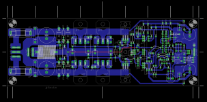
I did my own layout to suit components/heat-sinks/case materials on hand - hope you do not mind....
The heat-sinks are 12"x3"x1.5" flat backs, same height as my PCB, so the TO-3P packages end up close to the top/bottom edges of the heat-sink.
Power supply will be 40+40 VDC.
Based on your experience, do you think I will have thermal stability issues due to the placement of the drivers/Q13?
Hi OS,
Good to see you back!
I did my own layout to suit components/heat-sinks/case materials on hand - hope you do not mind....
The heat-sinks are 12"x3"x1.5" flat backs, same height as my PCB, so the TO-3P packages end up close to the top/bottom edges of the heat-sink.
Power supply will be 40+40 VDC.
Based on your experience, do you think I will have thermal stability issues due to the placement of the drivers/Q13?
Attachments
Hi OS,
Good to see you back!
I did my own layout to suit components/heat-sinks/case materials on hand - hope you do not mind....
Way to go!

nice layout discrete, but, if your power transistors fit under your PCB (I am assuming this), then your emmitter degen resistor solder pads will cause a problem. You need a bit more clearance. If you are using the short version resistors, you will not have this problem.
nice layout discrete, but, if your power transistors fit under your PCB (I am assuming this), then your emmitter degen resistor solder pads will cause a problem. You need a bit more clearance. If you are using the short version resistors, you will not have this problem.
Lazy, Bonsai,
Thanks for the feedback!
Re. the solder pads above the power transistors, I was planning to have the board on 1/4" or 3/8" standoffs, so not touching the transistors. 10mm LS radial degen resistors like OS is using would be nice, but I only have 17mm axial on hand.
Hi OS,
Good to see you back!
I did my own layout to suit components/heat-sinks/case materials on hand - hope you do not mind....
The heat-sinks are 12"x3"x1.5" flat backs, same height as my PCB, so the TO-3P packages end up close to the top/bottom edges of the heat-sink.
Power supply will be 40+40 VDC.
Based on your experience, do you think I will have thermal stability issues due to the placement of the drivers/Q13?
i like this layout better because of its symmetry.....i have 150mm high heatsinks which will accommodate this board better....
any chance to make "more pairs" options?😀
i like this layout better because of its symmetry.....i have 150mm high heatsinks which will accommodate this board better....
any chance to make "more pairs" options?😀
3? 🙂
Note my board miss a few components (css trimmer, dc offset trimmer, fuse bypass resistors), and is much more limited with regards to component sizes.
It also comes with no guarantees against errors or omissions...

Last edited:
Just a few "tweaks".....
I suppose one can not please everyone. 😀 BUT .... for this PCB format , I think the artwork /BOM is flawless.
Below (attached) , I have both the layout,schema and BOM. If these are "right on" (physically) , we can haggle about substitutes and/or sourcing later.
I did take Casull's capacitor recommendations , and re-positioned some components to allow for more space. 99% of the amp remains the same , as this layout still seems to offer the best "universality".
Some call for more outputs ... Crazy !!! 3 pair of NJW/MJL output devices can really "rock the house" ... 150w/8R and at 60v rails , 300w peaks.
If any can find any discrepancies between the 3 items below ......(BOM,schema,PCB) , please inform me. 100's of eyes are far superior to just 2 old ones 😀 .
OS
Attachments
Hi OS,
Based on your experience, do you think I will have thermal stability issues due to the placement of the drivers/Q13?
There should be no difference thermally.
OS
You still need to correct the errors in the BOM - see C3/C4 and others... Perhaps you can use my revised BOM as a reference?I suppose one can not please everyone. 😀 BUT .... for this PCB format , I think the artwork /BOM is flawless.
Below (attached) , I have both the layout,schema and BOM. If these are "right on" (physically) , we can haggle about substitutes and/or sourcing later.
I did take Casull's capacitor recommendations , and re-positioned some components to allow for more space. 99% of the amp remains the same , as this layout still seems to offer the best "universality".
Some call for more outputs ... Crazy !!! 3 pair of NJW/MJL output devices can really "rock the house" ... 150w/8R and at 60v rails , 300w peaks.
If any can find any discrepancies between the 3 items below ......(BOM,schema,PCB) , please inform me. 100's of eyes are far superior to just 2 old ones 😀 .
OS
- Home
- Amplifiers
- Solid State
- diyAB Amp - The "Honey Badger"