increased tail current, increased slew rate....
how about bypassing the 33 ohm resistor R20 with say 470/6.3v cap? this will increase your open loop gain due to increased VAS trannie transconductance...
how about bypassing the 33 ohm resistor R20 with say 470/6.3v cap? this will increase your open loop gain due to increased VAS trannie transconductance...
If you mean the VAS emitter resistor, the discussion a few days ago still applies. Notably post #2268.
Loopback Results & More
Hi keantoken,
Please find attached the results you were interested in.
Mouse over the thumbnails to see the filename which contain the test conditions.
The TPC network is appears to be connected correctly. 🙂
Regarding the VAS and R23, I did start off at 4.7 ohms as you suggested but found the square wave response improved as I increased
the resistance value until I reached the optimal value of 10 ohms. This is when things started to degrade again.
I was talking to Sandro about this, and he believes that the minor loop may have been unstable at 4.7 ohms and improved as I reached the optimal value.
I'm looking forward to your comments.
Thanks for your time.
Stuart
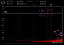
At 16KHz, does the distortion increase with loading or is it the same with no load?
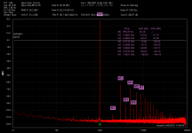
Check that your TPC network is connected correctly, as these prominent odd harmonics could be from an overloaded LTP. Looks like the effect extends down to 1KHz as well.
Did you check your analyzer output for harmonics?
Hi keantoken,
Please find attached the results you were interested in.
Mouse over the thumbnails to see the filename which contain the test conditions.
The TPC network is appears to be connected correctly. 🙂
Regarding the VAS and R23, I did start off at 4.7 ohms as you suggested but found the square wave response improved as I increased
the resistance value until I reached the optimal value of 10 ohms. This is when things started to degrade again.
I was talking to Sandro about this, and he believes that the minor loop may have been unstable at 4.7 ohms and improved as I reached the optimal value.
I'm looking forward to your comments.
Thanks for your time.
Stuart
Attachments
-
 Amplitude vs THD.png41.2 KB · Views: 381
 -
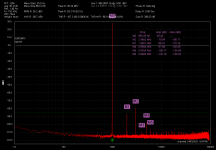 1K QA401 Loopback Test.png43.2 KB · Views: 381
 -
 16K QA401 Loopback Test.png45.8 KB · Views: 375
 -
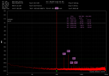 1K HB No Load Test.png43 KB · Views: 346
 -
 16K HB No Load Test.png46.1 KB · Views: 351
 -
 1K HB 8 ohm Load Test.png48.4 KB · Views: 113
 -
 16K HB 8 ohm Load Test.png46.2 KB · Views: 148
Last edited:
VAS current is around 8ma, so that the vas trannie 1/gm is (26mv/8ma) +33 ohms, or 3.25 + 33 = 36.25, now if you bypass the 33 ohms emitter resistor, then you end up with just 3.25 ohm, this represented a large increase in open loop gain...
VAS current is around 8ma, so that the vas trannie 1/gm is (26mv/8ma) +33 ohms, or 3.25 + 33 = 36.25, now if you bypass the 33 ohms emitter resistor, then you end up with just 3.25 ohm, this represented a large increase in open loop gain...
Or it would, if the VAS wasn't current driven, as follows from post #2268.
I'm looking forward to your comments.
Thanks for your time.
Stuart
What is your load? I have had metal oxide load resistors and steel alligator clips cause unexpectedly high distortion but your case goes beyond that it seems. I would try measuring distortion before and after the output coil. That will confirm whether the problem is between input and output.
Also measure the ACV between the LTP bases at 16KHz while the distortion is present to see how far the LTP is being driven. Do this with 1k-10k resistors in series with the DMM leads to minimize impact on stability.
A standard troubleshooting practice would be to measure the voltage to ground at each transistor pin and write it on the schematic to make sure operating points are correct. If this were the first step in any fault finding mission a lot of problems would be solved very quickly.
As far as I can tell it's only the odd harmonics that are way out of line, the even harmonics are very low. This suggests to me something like magnetic hysteresis or a metal oxide resistor, or a mistakenly huge miller capacitor. I've gotten caps 10x too large a few times by accident. The markings are sometimes so vague I have to use a meter to measure them.
Or it would, if the VAS wasn't current driven, as follows from post #2268.
gm x rl is the universal gain equation, so it is obvious that a bypassed emitter resistor of the vas increased its gain..
What is your load? I have had metal oxide load resistors and steel alligator clips cause unexpectedly high distortion but your case goes beyond that it seems.
I would try measuring distortion before and after the output coil. That will confirm whether the problem is between input and output.
........ or a mistakenly huge miller capacitor. I've gotten caps 10x too large a few times by accident. The markings are sometimes so vague I have to use a meter to measure them.
Hi Keantoken, thanks for the response.
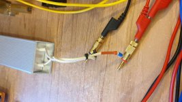
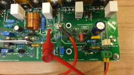
As you will see in the photos I believe that all connections are solid and not contributing to the problem.
The 8 ohm load itself possibly but from what I have seen this is the resistor other people use.
I have 3 of these amplifier modules built up and all exhibit this large distortion at 16khz.
I will investigate your other points and get back to you.
As you can see I was easily able to measure the miller caps with the meter I have and the kelvin clamps for zeroing out the lead resistance.
I'll post again when I have more info.
Thanks again
Stuart


Hi Tony, I think we both know that it's not about what it sounds like. It's about producing a amplifier with low distortion. This current distortion is not showing itself through simulation and I believe that it's worth further investigating.stuartamp, how is the sound btw with that level of thd at 16khz?
Wow, 3 amps all with the same problem. That adds some perspective. Too bad I can't inspect the layout.
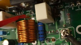
Everything between the feedback point and the load return is capable of causing distortion from magnetic saturation. I looked back at my measurements and I don't think it can cause the level of distortion you are seeing. But then, that is an enormous output coil, far larger than what I had and there is steel hardware nearby.
The amount of high order odd harmonics isn't explained by resistor or magnetic distortion. This seems more like crossover distortion. But you already reduced the driver bias resistor. Try measuring bias voltage at drivers and at outputs at 16KHz to see if it drops low? HF output at power is one area where this amp struggles in simulation due to the low driver bias.
Last edited:
Will do... thanks for the extra tip.Wow, 3 amps all with the same problem. That adds some perspective. Too bad I can't inspect the layout.
Everything between the feedback point and the load return is capable of causing distortion from magnetic saturation. I looked back at my measurements and I don't think it can cause the level of distortion you are seeing. But then, that is an enormous output coil, far larger than what I had and there is steel hardware nearby.
The amount of high order odd harmonics isn't explained by resistor or magnetic distortion. This seems more like crossover distortion. But you already reduced the driver bias resistor. Try measuring bias voltage at drivers and at outputs at 16KHz to see if it drops low? HF output at power is one area where this amp struggles in simulation due to the low driver bias.
Have a look at my build library and you will see that I did test and measure the output coils inductance.
First Amplifier build - Google Photos
gm x rl is the universal gain equation, so it is obvious that a bypassed emitter resistor of the vas increased its gain..
Okay granted, but the miller cap is the dominant source of distortion at 1KHz and beyond, so the best performing value of the emitter resistor is actually the one which allows the lowest stable miller capacitance.
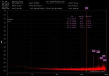
The odd harmonics seem to be rising faster than 6db/oct with frequency. In fact the difference at 1KHz an 16KHz is 83x for just a 16x increase in frequency. Nonlinear resistors and inductors do not do this.
I guess the tests so far would be:
16KHz loaded distortion at 3 points: before the inductor, after the inductor and at the feedback resistor.
Check the ACV across the hum breaker resistor to make sure nothing funny is happening with ground loops.
Check ACV between the LTP bases with 1k-10k resistors in series with the DMM probes. This will show if the LTP is overloaded.
THD vs frequency with individual harmonics would be interesting to see, as well as THD vs output power at 16KHz. If it is a dynamic bias issue, then there will probably be some breakaway point in frequency or power.
Thanks
Found it. Just about to post the results. Thank you so very much. Your support has made this possible.
Hi Tony, I think we both know that it's not about what it sounds like. It's about producing a amplifier with low distortion. This current distortion is not showing itself through simulation and I believe that it's worth further investigating.
maybe you are looking for another amp, another topology....good luck with that...this badger may not be it...
or you can try input pnp ltp cascode and npn VAS combo....i prefer npn VAS since it is intrinsically faster...
The odd harmonics seem to be rising faster than 6db/oct with frequency. In fact the difference at 1KHz an 16KHz is 83x for just a 16x increase in frequency. Nonlinear resistors and inductors do not do this.
I guess the tests so far would be:
16KHz loaded distortion at 3 points: before the inductor, after the inductor and at the feedback resistor.
Check the ACV across the hum breaker resistor to make sure nothing funny is happening with ground loops.
Check ACV between the LTP bases with 1k-10k resistors in series with the DMM probes. This will show if the LTP is overloaded.
THD vs frequency with individual harmonics would be interesting to see, as well as THD vs output power at 16KHz. If it is a dynamic bias issue, then there will probably be some breakaway point in frequency or power.
Hi again keantoken, I will review and take a look at all your notes over the weekend when I have a bit more time. Don't worry I will be thoroughly testing and exploring your advise. But for now here are the amazing results.
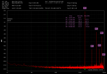
THD is now 0.00525% it was in the order of 0.23%
You were right there is something going on after the vouti node prior to the output inductor coil and zobel network.
Take a look when you can and maybe you can explain why this is happening and the best approach to fixing it.
Attachments
-
 16K HB 8 ohm Load Test - Across Load.png47.9 KB · Views: 271
 -
 16K HB 8 ohm Load Test - Pre Inductor.png44.8 KB · Views: 248
 -
 16K HB 8 ohm Load Test - Vout PCB.png45.3 KB · Views: 236
 -
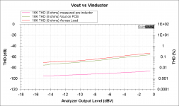 16K HB 8 ohm Load Test - Vout vs Pre Inductor vs VLoad.png37.5 KB · Views: 236
 -
 16K HB 8 ohm Load Test.png46.2 KB · Views: 249
 -
 Measured Across Load.jpg78.6 KB · Views: 159
 -
 Measured at Vout.jpg95.2 KB · Views: 169
 -
 Measured Pre Inductor.jpg69.6 KB · Views: 193
Last edited:
Wow, that is very surprising. The 3rd harmonic increases by 56x after the inductor!
This pretty well rules out the LTP overload hypothesis.
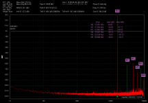
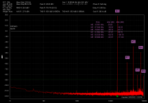
The remaining mechanisms which can cause a harmonic voltage across the inductor are magnetic objects nearby, and harmonics present in the load current due to perhaps a nonlinear load resistor. If the load resistor is wirewound maybe it has magnetic mounting hardware inside that is causing nonlinearity.
One thing you can do to test the inductor is to locate it off board with a twisted pair of wires, then you can flop it down wherever you want.
However I see that the difference in 3rd harmonic when THD is measured at the load vs at the PCB output is about 3db. So there must be something nonlinear between the PCB and the load return point. Most likely the resistor itself, but I've occasionally had distortion come from connections.
Since the THD at load closely follows the THD after the inductor, I'm tempted to think that the load resistor is nonlinear and the load wires are just acting like an extension of the inductor, hence there is higher THD a the load.
Can you test the load resistor with the LCR meter to see how inductive it is?
This pretty well rules out the LTP overload hypothesis.
The remaining mechanisms which can cause a harmonic voltage across the inductor are magnetic objects nearby, and harmonics present in the load current due to perhaps a nonlinear load resistor. If the load resistor is wirewound maybe it has magnetic mounting hardware inside that is causing nonlinearity.
One thing you can do to test the inductor is to locate it off board with a twisted pair of wires, then you can flop it down wherever you want.
However I see that the difference in 3rd harmonic when THD is measured at the load vs at the PCB output is about 3db. So there must be something nonlinear between the PCB and the load return point. Most likely the resistor itself, but I've occasionally had distortion come from connections.
Since the THD at load closely follows the THD after the inductor, I'm tempted to think that the load resistor is nonlinear and the load wires are just acting like an extension of the inductor, hence there is higher THD a the load.
Can you test the load resistor with the LCR meter to see how inductive it is?
Last edited:
- Home
- Amplifiers
- Solid State
- diyAB Amp - The "Honey Badger"