Thank you very well, Stuart!
I'd say your results had to be expected, as the devices you've chosen and measured aren't that different in their electrical specs, all in all.
Best regards!
I'd say your results had to be expected, as the devices you've chosen and measured aren't that different in their electrical specs, all in all.
Best regards!
Yes. But why is the distortion ~0.003% at 1khz at 80watts into 8ohms and ~0.23% at 16khz at 80watts into 8ohms even though its very stable at a unity gain crossover frequency of just over 1Mhz. I would assume that at that frequency there is plenty of negative feedback available to reduce the distortion. More than what I'm seeing anyways....Thank you very well, Stuart!
I'd say your results had to be expected, as the devices you've chosen and measured aren't that different in their electrical specs, all in all.
Best regards!
Yes, but the reason must be anywhere else than in the - rather similar - power devices.
I'm scratching my head why no one else didn't notice yet what you've found out.
Best regards!
I'm scratching my head why no one else didn't notice yet what you've found out.
Best regards!
thd is often quoted at 1khz with the harmonics going down many db below.....
at 16khz? that is the threshold of hearing, what does it matter? i wonder..
mine is at 12khz.....i am 68....
at 16khz? that is the threshold of hearing, what does it matter? i wonder..
mine is at 12khz.....i am 68....
Last edited:
At 16KHz, does the distortion increase with loading or is it the same with no load?
Check that your TPC network is connected correctly, as these prominent odd harmonics could be from an overloaded LTP. Looks like the effect extends down to 1KHz as well.
Did you check your analyzer output for harmonics?
Check that your TPC network is connected correctly, as these prominent odd harmonics could be from an overloaded LTP. Looks like the effect extends down to 1KHz as well.
Did you check your analyzer output for harmonics?
At 16KHz, does the distortion increase with loading or is it the same with no load?
Check that your TPC network is connected correctly, as these prominent odd harmonics could be from an overloaded LTP. Looks like the effect extends down to 1KHz as well.
Did you check your analyzer output for harmonics?
Thanks for the response.
I'll check my TPC connections and I'll post some loopback tests and some no load tests tonight. I do know that the no load measurements are significant lower.
Last edited:
If the tail current were the problem then it would show up in simulation. I suppose it is possible that the LTP is being starved of tail current due to a fault, but that should show up in slew rate.
I'm accused of running too low of a tail current.
I'm using a blameless type amp that runs 4mA+ tail , but that is with old
2N5401's.
OS
I'm using a blameless type amp that runs 4mA+ tail , but that is with old
2N5401's.
OS
that 16khz distortion increase could be the result of slewing imho....incremental increase in tail currents, not big jumps is what i propose...
i am not a fan of simulations, sorry......
i am not a fan of simulations, sorry......
I'm accused of running too low of a tail current.
I'm using a blameless type amp that runs 4mA+ tail , but that is with old
2N5401's.
OS
Leach like to run 4ma too, and he said increasing that more increases noise...
Hugh, otoh like small tail currents....
maybe time to consider the jfet inputs, Cordell in his recent lectures at the burning amp festival talked about it...
I can't get the badger sim to do much over .01% 20K in simulation.
I know the sim is right , the new Badger ... I did not know how the British
builder got 5 PPM out of the design ??
I used this Badger's TMC with the new EF3 badger ... guess what - it simulated
at 4.6ppm.
The guy in England .. he showed his AP analyzer results.
I would suggest to go back to just a 68pf CMC on the VAS and and increase
emitter degeneration on the LTP pair.
.02-.03 % should be worst case with this basic topology.
OS
maybe time to consider the jfet inputs, Cordell in his recent lectures at the burning amp festival talked about it...
Too bad they don't make them anymore. Russians still make tubes !
OS
As shown its a 6mA tail current with 130ohm emitter degeneration resistors which gives you an effective degeneration of 100ohm after you take into account the 1k trimpot for dc offset adjustment
Too bad they don't make them anymore. Russians still make tubes !
OS
Nelson Pass has tons of them, and probably John Curl, our diyaudio store sells then from time to time...
2016 Burning Amp Festival speaker: Bob Cordell - YouTube
As shown its a 6mA tail current with 130ohm emitter degeneration resistors which gives you an effective degeneration of 100ohm after you take into account the 1k trimpot for dc offset adjustment
tail current is 3.7ma as per schematics at post #2
did you set that to 6ma when you tested?
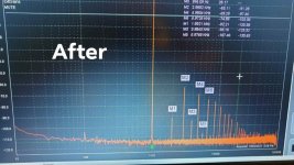
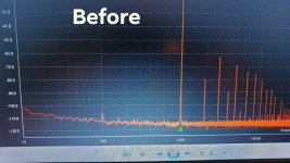
Of course I had it set to 3.75mA when I first built my test Amplifier module. Over the past few months I have preformed many, many test, one of them was increasing the tail current from 3.75mA to 6mA and changing the emitter degeneration resistors. In doing so I noticed a large improvement in the second and fourth harmonic. See attached.tail current is 3.7ma as per schematics at post #2
did you set that to 6ma when you tested?
I was reading douglas self book on input stage design and he says that you will get a more linear input stage by increasing tail current to increase GM then reduce it again by increasing degeneration and adjusting the compensation capacitors to suit
So that's what I did.


- Home
- Amplifiers
- Solid State
- diyAB Amp - The "Honey Badger"
