Hi UncleMud,
The very best oscilloscope you could pick is an analogue model. The best news is that they are only a couple hundred for really excellent scopes that were over $1K new. A digital scope has toys, but they can lie to you. They are also very noisy (the trace). For a digital, you need 4x to 5x the bandwidth as an analogue. So what that means is that my 1 GHz digital is about the same as a 200 MHz analogue scope. I kept my analogue scopes.
The very best oscilloscope you could pick is an analogue model. The best news is that they are only a couple hundred for really excellent scopes that were over $1K new. A digital scope has toys, but they can lie to you. They are also very noisy (the trace). For a digital, you need 4x to 5x the bandwidth as an analogue. So what that means is that my 1 GHz digital is about the same as a 200 MHz analogue scope. I kept my analogue scopes.

Please check neither D1 and D2 are open. Also search the thread for posts by me on D3 an R19.
Good luck
Good luck
Moderator, I am so sorry. I posted my issue in the wrong thread. Holy smokes! What a day! Time for a break. I meant to post in: FH9HVX- Budget Conscious 100 W Class AB for lean times. Feel free to move my posts from today if you can. So sorry.
My Honeybadger is seriously ill and I am looking for a cure. After about four years of perfect performance one channel developed a warbling/scratching background-noise that starts on powering-up and stays constant in content and volume independent from temperature, input and output loading. Both channels use a common power supply. The noise is not that loud and masked at a medium sound level. It feels like a transistor gone rogue.
Last weekend me and the badger attended a meeting of enthusiasts, some much more knowledgeable regarding electronics than myself. After spending a couple of hours with checking the PCB / soldering points and replacing everything semiconductive from Q1 to Q13 even the experts ran out of ideas. The badger is still warbling. Anyone here with a clue?
Right now the only promising solution seems to build one completely new board from scratch ...
Please search this thread for posts by me about R19 and D3. Replace those with the parts I suggest and also check D1, D2
You say that you have run it for four years before it started to misbehave recently, right? If nothing else helps, I have a pair of untouched spare boards, purchased about four years ago, which I do not plan to use. Happy to send them over from CH, if needed. Good luck with the repair, though!
Scope the warbling. BTW , what the heck is "warbling" ?The badger is still warbling. Anyone here with a clue?
Another trick , when it does warble spray some freeze spray on every component.
Since a full semi swap failed , don't discount the caps or resistors.
In fact , restuff a whole PCB- complete.
Did the semi swap include the diodes ? they are junctions , too.
OS
There is some junk out there...Resistors with poor cap attachments are famous for this.
With the new modular Wolverine/spooky , especially the spooky - only costs 7-8$ for as whole input stage.
No use fixing it - just keep a few extras to swap out.
Badger boards could take a few swaps , pretty durable.
OS
Hello all,
many thanks for your input. I just tried the proposed swap of R19to 15k and replaced the 1.3W Zener with a 500mW type - no change.This does not really sound like oszillation, it is a scratching/crackling/warbling noise.
How to attach an (existing) MPEG4-recording? The "attach files" option does not show the file.
The board and the solder joints were checked by various (experienced) guys and I did some "reheating" wherever quality seemed in any way questionable.
By the way, one of my ground rules: NEVER ebay or aliexpress for electronic components or boards !
Thank you "mcsontos", but I make the boards myself (one in blue would look strange) ...
Looks like you also have protection boards. Have you tried flipping channels on those to rule them out?
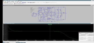
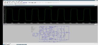
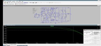
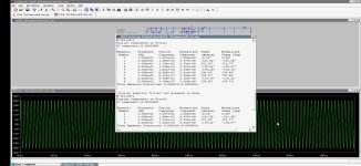
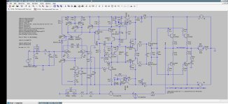
Tried to modify HB, don't know about Ltspice accurate or not or cirquit is wrong, hope it's works ,
Attachments
-
 Screenshot_20241012-215912.jpg270.5 KB · Views: 120
 -
 Screenshot_20241012-220106.jpg171.1 KB · Views: 110
 -
 Screenshot_20241012-220441.jpg160.5 KB · Views: 112
 -
 Screenshot_20241012-220013.jpg173.5 KB · Views: 100
 -
 Screenshot_20241012-215628.jpg270.4 KB · Views: 111
 -
 Screenshot_20241012-221009.jpg208 KB · Views: 121
beautiful
No enclosure from the shelf - custom design by myself. Bottom and sides from phenolic resin coated plywood, front standard anodized 3mm aluminum 2U, rear aluminum spray painted. Tops I don´t do (no grandchildren yet).
manic mechanic,
pleasing layout and finish, indeed! Optimized board placements, short and spatially well separated air-wires, no mess, etc. Just beautiful. 🙂
I had a coffee-break chat with my reliability colleagues who hunt such things 7/24. Assuming that you swapped everything in the environment (left-right cables, speakers, source cables, source itself, protection boards etc) and checked for GND faults, their further suspects are:
Since it is not a matter of lawsuit (in which case they routinely do high-res thermal maps, X-rays, electron microscopy etc), they also recommend to simply redo the whole board from the scratch.
pleasing layout and finish, indeed! Optimized board placements, short and spatially well separated air-wires, no mess, etc. Just beautiful. 🙂
I had a coffee-break chat with my reliability colleagues who hunt such things 7/24. Assuming that you swapped everything in the environment (left-right cables, speakers, source cables, source itself, protection boards etc) and checked for GND faults, their further suspects are:
- aging of (potentially overheated or mechanically strained) film capacitors
- (aged) solder resin residuals between nearest neighbor solder pads
- soft dielectric breakdown of the pcb insulator between closely spaced, large potential difference lines/pads
Since it is not a matter of lawsuit (in which case they routinely do high-res thermal maps, X-rays, electron microscopy etc), they also recommend to simply redo the whole board from the scratch.
mcsontos,
many thanks for your praise and your input! I just ordered the missing bits and pieces for a new board from scratch.
If you work on a PCB too long changing and re-changing components, you very probably create more new "demons" than you care for ...
many thanks for your praise and your input! I just ordered the missing bits and pieces for a new board from scratch.
If you work on a PCB too long changing and re-changing components, you very probably create more new "demons" than you care for ...
- Home
- Amplifiers
- Solid State
- diyAB Amp The "Honey Badger" build thread