Hello guys,
I am building a Badger but I am not an electonician.
Is it important to have the same Hfe for Q10 & Q12?
I just tested a lot of 40 NPN and 40 PNP
Q10 -PNP : Hfe average = 200
Q12 - NPN : Hfe average = 90
Vce are very similar. + ou - 1,6% on 80 transistors (40 NPN and 40 PNP)
And it is easy to found one pair with the same value.
Hi all,
I'm building a new amp board. Following the 2.5.4 schematic I note that C4 has changed from 220uf to 100nf 100V. I have spent significant time trying to locate that capacitor with a 5MM lead spacing. Really looked around the corner. Appreciate if anyone has some spares or can point me in the right direction.
I'm building a new amp board. Following the 2.5.4 schematic I note that C4 has changed from 220uf to 100nf 100V. I have spent significant time trying to locate that capacitor with a 5MM lead spacing. Really looked around the corner. Appreciate if anyone has some spares or can point me in the right direction.
On the schematic v2.5.4 I have, C3 is 220uF, C4 is 100nF. They are in parallel with each other.
Not critical, and it will be difficult to find matching Hfe between NPN and PNP pairs. Q10 and q12 are in series with each other, therefore will have same current.Is it important to have the same Hfe for Q10 & Q12?
Assume the same for C9 - that I can use a 22uF 100V cap?100V is fine there.
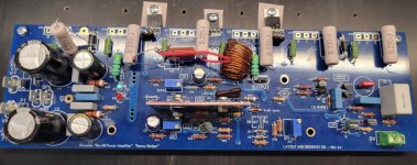
I have a new board ready for initial test.@Chiptech starting fresh at this point is probably a good idea.
Take your time.
Measure and confirm each component before you install it.
Clean your board thoroughly before you apply power.
Use a magnifier light to check that you don't have any solder bridges between pads.
Use a regulated supply for your initial start up.
You can also verify the board without the output transistors installed if you like.
This allows you to use a 50mA limit on your regulated supply so there is little chance of component damage even if something is wrong.
Just follow my image attachment.
Once you verify the board you can install the outputs.
Do I have this set up correctly? I'm not quite sure about where to connect the center tap to the R43 output trace.
Can I use this with the DBT as I don't have a regulated supply?
If not, I'll think harder about acquiring one.
Attachments
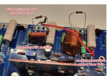
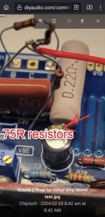
The resistors you have in place of the output transistors are doing the same thing as the two 75 ohm resistors. Two different methods of doing the same thing. Use one method or the other, not both.
You need to install the drivers (Q14 & Q15) and the bias spreader transistor (Q13) before doing this.
You can do this with the DBT
You need to install the drivers (Q14 & Q15) and the bias spreader transistor (Q13) before doing this.
You can do this with the DBT
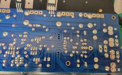
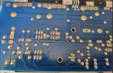
Its a bit hard to see exactly were you have the wire going from the centre of the Two 75R resistors. It just need to go to any node on the output trace. The bottom of R46 for example.I have a new board ready for initial test.
Do I have this set up correctly? I'm not quite sure about where to connect the center tap to the R43 output trace.
Can I use this with the DBT as I don't have a regulated supply?
If not, I'll think harder about acquiring one.
I'm not sure what the resistors from Base to Emitter are for. Personally I have never done that.
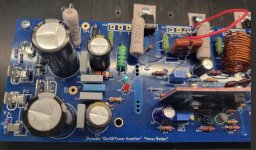
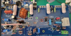
Yes... All transistors should be installed.
And you should some more images of the board. Top and bottom.
I've never used a DBT.
What you use for regulation is up to you. The safest method is using regulated supplies as I showed in my youtube video. Maybe you can put a shout out on the forum for someone near you to help you with this and you could vist their place.
Attachments
See photos below.
I have the centertap soldered to the R46 resistor.
Below is a powering up checklist and bias plan:
Pre-flight Check List
Set pots:
R7 set to 80R
R17 to midpoint
R30 sent to max resistance
Attach power from PSU: V+, Ground, V- [Grd goes to left grd tab]
Connect DMM’s
10R resistor
TP1 & TP2
Across R14
Ist [Quick On-Off] Test With DBT
Read DCV across 10R resistor = close to 0V
LEDs turn on
2nd Test – Initial Biasing With DBT
Connect DMM to speaker output – speak grd
Adjust bias:
R7 = 8.25V
R17 = > 0.5V
R30 = 15-20mV
3Rd Round With DBT
Remove 10R resistors
Install 4A slow blow fuses
Remove center tap and install R36
Install output transistors
Tune Bias
4th Round
Remove DBT
Final bias adjustments
Appreciate any further thoughts, otherwise, Sunday its game day.
Attachments

Chiptech,
Is this a new board you built, or did you redo the old amp board? Also, the parallel contribution of C3 and C4 needs to be at least 100uf. In this case, there should be a 220uf (preferably non polar) there. The bypass cap is just a nice option. I think the schematic goofed on the part number as it pertains to the silkscreen, which is why it might be confusing for some folks. This is part of the feedback section and it is important.


Best,
Anand.
Is this a new board you built, or did you redo the old amp board? Also, the parallel contribution of C3 and C4 needs to be at least 100uf. In this case, there should be a 220uf (preferably non polar) there. The bypass cap is just a nice option. I think the schematic goofed on the part number as it pertains to the silkscreen, which is why it might be confusing for some folks. This is part of the feedback section and it is important.
Best,
Anand.
Last edited:
Anand,
This is a new board. I got direction on C4 as I was not finding the right cap. I wondered about the part in there currently.
Thanks for the call out.
Chip
This is a new board. I got direction on C4 as I was not finding the right cap. I wondered about the part in there currently.
Thanks for the call out.
Chip
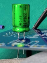
Forgot to mention I have searched high and low for a non-polarized 220uF 100V cap with a 5mm lead spacing. If anyone has a part number for one, I'd appreciate your input.
That cap will only see a few volts in normal operation. The only time it would see higher voltage is if the amplifier failed and went DC on the output. 50V should be fine there.
You can use a 6V3 cap and back-to-back LEDs across it to prevent it exploding on amp failure. Also provides visual indication of the amp jamming at the rail. Surprized this amp doesn't use a trick like that, it makes it easy to have more capacitance in a small size.
- Home
- Amplifiers
- Solid State
- diyAB Amp The "Honey Badger" build thread