If you have only 12V zener then you might try changing R19 first. If it did the trick then its OK, if not change zener to 15V but apparently 12V should work. I have 15V zener in mine and 47k resistor I think. I think Stuart sent you the latest schematics, resistor value is even lower, namely 15k but you might have other problems as Stuart pointed out. I did not read your posts prior to the diode question so I responded only to that. If you tested every component before soldering it and did not make any mistakes then quality of soldering of some of the components might be a problem.Try R19 at 27K before adding the zener? Not quite clear on that.

Thanks. Cleaned them up, along with a few others.
But when I connect the amp board up, I don't get any juice to it. Leds don't light up and no readings on the multimeters.
I think I'm going to try a fresh board. I've learned a hell of a lot with this one.
But when I connect the amp board up, I don't get any juice to it. Leds don't light up and no readings on the multimeters.
I think I'm going to try a fresh board. I've learned a hell of a lot with this one.
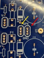
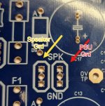
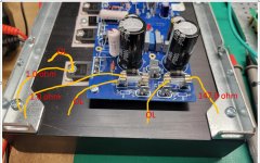
Your PS must have three terminals: negative, positive and ground. You connect PS ground to onboard ground which has two terminals, one for PS ground and one for speaker ground. Your yellow and red arrows point to these GROUND terminals. You connect PS negative to V- terminal on the board and NOT to where you connected it (yellow arrow), that is GROUND TERMINAL. You connect your PS positive to V+. Remember: your PS must have THREE (3) terminals: positive, GROUND and negative. PS Negative goes to V- on your HB board, Positive PS goes to V+ on your HB board and PS Ground goes to board Ground described as SPK GND as it has two terminals. The other Ground is for your Speaker.No voltage. No LED lights.
My PSU board is putting out 63DCV +/-
The negative from the PSU goes to the ground [yellow].] and the TP1/TP2 DMM lead goes to the adjacent ground [red].
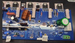
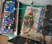
BUT before doing the above check your board for possible joint connections on heatsink transistors shown on photos.
Remember that you connect power through a globe to prevent burning something. If globe goes bright for a second or two and then gets dim then it's OK and you can continue with initial adjustments. After that you disconnect globe and power on your amp directly for final adjustments. Input should be shorted and nothing attached to the output. If all is OK after 30 minutes then you connect a dummy load of minimum 100W and 8-10 ohm. TEN ohm dummy load has advantage of making calculations easy, can be done in ones memory. With that load you adjust what has to be adjusted (bias, offset etc).
Once everything measures fine you connect audio generator to the input and an oscillator to the output. You can see how sine and square waves of various frequencies are amplified. If you do not have oscilloscope and generator you skip this testing stage. Eight and Four ohm dummy loads are real loads for final FINAL adjustments before actual speaker is connected and music goes to the input.
cheers,
The fuses were blown. They don't change visual appearance when they blow.Have you checked voltage on each end of each fuse?
I put new ones in and this time the fuse for the PSU blew.
I will review janusz guidance above in the morning. Too late tonight to do anything but say thanks for all the assistance.
If he connected PSU negative terminal to the board ground (yellow arrow) he shorted it so blown fuses.
It will be best if you showed us details of your wiring of the completed board.The fuses were blown. They don't change visual appearance when they blow.
I put new ones in and this time the fuse for the PSU blew.
I will review janusz guidance above in the morning. Too late tonight to do anything but say thanks for all the assistance.
@Chiptech unfortunately if you have found any pads that have been mistakenly bridged by solder you are going to have a big job on your hands to fix the problem as multiple components could be blown and will need replacing. Its vitally important to check and verify these sorts of things before you attempt to apply power.
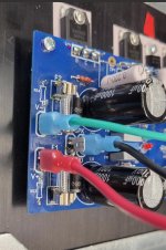
It looks like you have it connected correctly, but you should verify the output transistors aren't shorted before trying to power it up again.
@Chiptech its best to verify this with a DMM preferably two DMM's before you even connect anything to your amplifier pcb.Have I sorted this correctly?
You may want to review this video I made for one of the wolverine builders.
Psu wiring
- Home
- Amplifiers
- Solid State
- diyAB Amp The "Honey Badger" build thread