Honey Badger Power Supply Question:
I just finished building, and just started testing my Honey Badger amp.
It passed the Dim Bulb smoke test, I installed the fuses, and connected one amp board to the power supply.
While testing, I noticed the resistors in the power supply were getting hot.
I only had one amp channel connected, and the 2.2K 3 watt resistors were HOT (120 degrees F)
Do I have the correct values for the resisters on the Cap Filter boards, or just the wrong wattage?
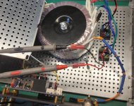
I’m using an Antek AN-8445 toroid and the diyAudio universal power supply boards, with discrete diodes. I don’t have any snubbers or other caps on the boards. Each filter board has 4 x 10,000 uf 80 volt caps and 4 x 0.47R 3watt and 1 x 2.2K 3watt resistor.
Rails are showing about 61-0-61 volts with one amp board connected.
I just finished building, and just started testing my Honey Badger amp.
It passed the Dim Bulb smoke test, I installed the fuses, and connected one amp board to the power supply.
While testing, I noticed the resistors in the power supply were getting hot.
I only had one amp channel connected, and the 2.2K 3 watt resistors were HOT (120 degrees F)
Do I have the correct values for the resisters on the Cap Filter boards, or just the wrong wattage?
I’m using an Antek AN-8445 toroid and the diyAudio universal power supply boards, with discrete diodes. I don’t have any snubbers or other caps on the boards. Each filter board has 4 x 10,000 uf 80 volt caps and 4 x 0.47R 3watt and 1 x 2.2K 3watt resistor.
Rails are showing about 61-0-61 volts with one amp board connected.
Attachments
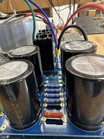
Where in the circuitry are these resistors located? Are they in parallel with the DC rails? So, each one dissipates 61²/2200 = 1,7 W, hence will get hot indeed.
Best regards!
Best regards!
Increase the bleeder value to 10k ~ 22k, 3 watt. For safety reasons place the LED's and put an appropriate warning on the board. 130V DC can be quit unpleasant.
Antek was very helpful and sent me a new 8445. That hummed too, so it went back.Jwilhelm,
I called Antek today and talked with John. He patiently worked with me, had me send a photo and decided he will send me a new unit and a return label so I can return this one to him.
So we will see. More will be revealed.
I'll start building a amp card.
I just did a DBT on turn on. The bulb flickers as the Marc J slow start board clicks several times [which it has never done before in any of my builds].
The clicking stops and the bulb is bright and then slowly dims out.
Could the slow start board be the source of my issue?
I've not seen a DBT do a "slowly dims out" routine.
Suggests to me a short somewhere.
thanks,
Chip
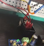
That's the relay. I think the TO220 device mounted in the heatsink is a triac. You can try bypassing that board completely and powering up the supply to see if the hum goes away. An 800VA transformer might blow a fuse if you start it at the wrong part of the AC circuit but it shouldn't hurt anything for a couple test cycles. Leave the light bulb in the circuit to act as a soft start.
I'm not aware of any issues using a triac for soft-starting. This is just a process of elimination to find the source of the noise in Chiptech's build. I haven't experimented with triacs but from what I've read the output waveform can de a little distorted. I'm wondering if this might be causing the core to saturate in his transformer.
From the way operation is described it's sounding like the soft-start isn't charging the capacitors fully before switching on the relay engages, but this may be due to the bulb being in series with the supply.
I had a quick look at the schematic for the soft-start board. The triac is there to power the supply at the zero crossing point of the mains AC cycle. There's an Antherm NTC resistor that does the actual soft-start of the supply. Then a relay bypasses all those parts. If this is the case it's actually the wrong part of the phase to energize the transformer, but this won't cause hum.

I had been using this soft-start board in my M2X amp and all was good. I had searched Mark's soft-start build forum for any mention of incapability when using it with the Badger amp and didn't find anything. I might have missed something. I will remove it and see if that isolates my issue.
Hi All,
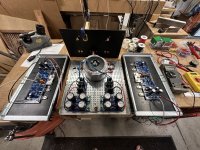
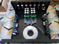
Just a quick mockup to see how things fit in the chassis. Was going to use this for another amp but have changed plans.
Still missing heatsinks, shall purchase those next from Conrads Aust. Also soft start/speaker protection. Will most likely go with Rod Elliott (P33, P39 & P198) for these items.
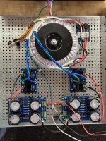
The plan is to go 'virtual'? dual mono, 1 transformer (45V AC 800VA) with 1 bridge and 1 psu per channel. 42,000 uF total shown (21,000uF/channel) in the current configuration.
The lid will be 2.5 - 3 mm aluminium plate from the local metal shop.
Open to suggestions and critique.
Thanks Richard

Just a quick mockup to see how things fit in the chassis. Was going to use this for another amp but have changed plans.
Still missing heatsinks, shall purchase those next from Conrads Aust. Also soft start/speaker protection. Will most likely go with Rod Elliott (P33, P39 & P198) for these items.
The plan is to go 'virtual'? dual mono, 1 transformer (45V AC 800VA) with 1 bridge and 1 psu per channel. 42,000 uF total shown (21,000uF/channel) in the current configuration.
The lid will be 2.5 - 3 mm aluminium plate from the local metal shop.
Open to suggestions and critique.
Thanks Richard
Attachments
Removed the soft start.I had been using this soft-start board in my M2X amp and all was good. I had searched Mark's soft-start build forum for any mention of incapability when using it with the Badger amp and didn't find anything. I might have missed something. I will remove it and see if that isolates my issue.
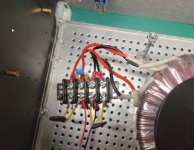
Built a new terminal block.
Connected everything up. Using 2.5-amp slow blow fuse and the fuse is good.
Used the DBT.
Using a 10000uF 80V X 8 PSU board with R1 thru R8 shorted [though I do see some folks filled them.
Turned it on at the DBT.
No light from bulb.
LEDs don't light up on PSU
Only get 0.008 DCV out of PSU. Prior readings were 62DCV +/- with soft start in place.
This has the feel that I'm missing something very obvious, but having pondered it for a while and compared this PSU set up to past ones of mine, I don't see it.
Attachments

What's the AC voltage coming out of the transformer? Sounds like you blew a fuse or have the transformer wiring messed up.
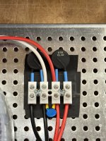
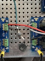
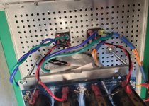
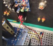
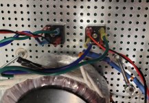
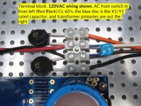
Post #5012 pictures, can you take a closer picture of the EIC plug wiring? Does that plug contain a 5X20 fuse? Also the last picture, why is there a thermistor between the two red primary windings? Primary windings are red and black and should be connected in parallel for 110-120V.
See photos. I'm using a 5X20 fuse 2.5AMP slow blow. I've wired the primaries as per my first F5 build.
Something I've done doesn't add up. I think I'm stuck in my paradigm.
Thanks
Something I've done doesn't add up. I think I'm stuck in my paradigm.
Thanks
Attachments
- Home
- Amplifiers
- Solid State
- diyAB Amp The "Honey Badger" build thread