Thanks gentlemen! I'm beginning to see there are a number of approaches that may be useful. I'm probably done testing for today but will pick things up again tomorrow.
Hi RickRay,Lead resisitance.
So part of my high readings may be the added resistance of the test leads themselves? Which I'm guessing is more of a factor at low resistance values.

Yes, usually your meter has a REL (relative) button which is used to null out the resistance of your leads first.So part of my high readings may be the added resistance of the test leads themselves? Which I'm guessing is more of a factor at low resistance values.
The ideal way to do this by talking a reading with a meter that supports a 4 wire connection. Google
4 wire resistance measurement
And
kelvin clips
The change that you will damage one yourself during an improvised measuring session is higher then the change you received a faulty one from Mouser. Just check the marking, and if you cant resist, use a DMM to see if it reads somewhere between 0 and 1. I used over 30 of the same 0.22 KOA resistors this year, all bought from Mouser, and all where good.
So I came up with a crude testing procedure for my 0.22 ohm KOA Speer resistors. I lined up six resistors side by side and soldered the tips of the adjoining leads. I then tested the six resistors in series and got a total resistance of 1.58 ohms. 1.58 divided by 6 gave me an average resistance of 0.2633 ohms, a much more likely scenario than my initial testing attempts. I snipped off the soldered tips afterwards and still had enough lead length for proper placement.
To address OmeEd's comment about the Speer resistors, I'm actually not too worried about faulty components since 99% of my parts come from Mouser or DigiKey. My main reason for testing is so that I know the value of unmarked components before I place them. I knew it was unlikely that my new resistor was bad, but when I got two in a row that were off I guessed something else was going on.
Thank you to everyone who took the time to comment and offer feedback. I appreciate your knowlege and patience. Dave M.
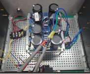
I'm back. I'm totally stumped. I have yet to build s HB amp board because I had a hum from my transformer/PSY board.To-date all I have built and assembled is the PSU.
I removed Mark Johnson soft start, which i really like, to see if that was the cause. Nope. Still has a hum. Then things took a turn.
I could only get i2o AC V at the terminal. Negligible current out of the secondaries. No DCV from the PSU. Leds don't lite up.
So I swapped out the Antek 8445 and replaced it with the Antek transformer and PSU i used in my M2X build. And I get the same result.
I replaced the IEC with a new one. I replaced one of the 35A Bridge rectifiers.
Same results.
Check the fuse. Good. Something real simple is gumming up the works here.
I'm back. I'm totally stumped. I have yet to build a HB amp board because I had a hum from my transformer and wanted to sort that out first.This just in. My wife says she can hear a very low hum. Wearing hearing aids, I can't.
It's less then with the soft start board in.
The mystery continues.
I removed Mark Johnson soft start, which I really like, to see if that was the cause. Nope. Still has a hum.
Then things took a turn downward. Now I get no hum or current from the transformer????
I read 120 AC V at the terminal. But negligible current out of the secondaries. No DCV from the PSU. LEDs don't lite up on the PSU board.
I swapped out the Antek 8445 and replaced it with the Antek transformer and PSU I used in my M2X build. And I got the same result. No hum, no current.
I replaced the IEC with a new one. I replaced one of the 35A Bridge rectifiers.
Same results.
Checked the fuse. Good. Something simple is gumming up the works here.
But I can’t see it.
Attachments
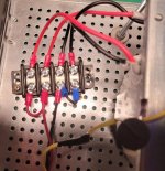
Do you have jumpers on the terminal block to connect the two windings in parallel? You need both red secondary windings connected to the red wire from the IEC and both black secondary windings connected to the black wire from the IEC. You also need bigger gauge wire from the IEC to the terminal block, but that can wait, it isn't this problem.
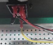
Looks like the primaries of the transformer are connected wrong. If you are running on 120VAC connect red to red and black to black. If you are running 240VAC you need to connect the primaries in series and phase them correctly.
Both red leads of the transformer need to be connected together to mains power or neutral. Both black leads need to be connected together to mains power or neutral. As is you are either connecting only half of the primary windings to mains power or only one lead of each primary to mains power. There are four wires in the primary windings for a reason. They all need to be connected to something.
Are you getting 120V out of the IEC module? Your meter is set to measure AC instead of DC?
That wire is too light for the job. It should work for testing but it will likely get pretty warm during high power testing. You should be using minimum 16 gauge there.
I can see in this picture that you have one lead from each primary winding connected, so even if you do have 120V reaching the terminal block you won't have any output.
Dazed and confused. It's been a day. 120 ACV at terminal. Check.
I returned the CL-60's that I've used in my FW amps. I was directed not to use them for the HB. But with them in I have 64.2 DCV +/- at the PSU.
The CL-60's bridged the terminal side wired to the IEC and I get full power. But going forward, I should remove them and use something to bridge the +/- connections on the side that the IEC wires [now 16 gauge] connect to. Is that correct? What is normally used?
Finally, if there is a hum, it's so low now that I can live with it.
And thanks.
Attachments

So are the 4 terminals on the bus bar independent until jumpered? Puttling the CL-60s across the terminals completed your primaries. Just a guess. Good luck.
I believe they are. I am so down the FW amp rabbit hole, that moving on to the HB is like learning another language. At least I understand that now.
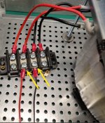
Replaced CL-60's with 16 G wire jumpers.
I intend to put my soft start back in place without the hum. But that's tomorrow's project.
Replaced CL-60's with 16 G wire jumpers.
I intend to put my soft start back in place without the hum. But that's tomorrow's project.
Attachments
Last edited:
Read the guage of the transformer promary wires, red and black. I'm betting they are 16 or 14 guage. You need at least the same guage wire from the IEC to the terminal block or soft-start. Better would be one guage bigger (lower in guage number) since you are driving two windings in parallel. So if your windings are 14 guage, I would run 12 guage from the IEC to the terminal board or soft-start.
- Home
- Amplifiers
- Solid State
- diyAB Amp The "Honey Badger" build thread