Sweet.. you did a great job with that. Well done. Its also get that you added a description of the process for other membersPics
Copy that... you need to put some good tension on the wire for it to hold its shape without some form of containment. I still haven't decided whether or not to put an air-gap between the coils... there are reasons for doing, or not.
I have enough wire to do a lot of trial and error, so I may give it a go.
I'll get some pics of the boards when I mount them... My caps are a little large and space was limited. I had to get creative to get everything mounted.
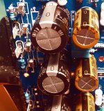
And a little cap porn... below.
I have enough wire to do a lot of trial and error, so I may give it a go.
I'll get some pics of the boards when I mount them... My caps are a little large and space was limited. I had to get creative to get everything mounted.
And a little cap porn... below.
Attachments
Last edited:
Making coil/inductor... If you are like a lot of us you want to know what the value of the coil is. It can be a little challenging for new people, or people that don't have a lot of test equipment.
I tested several ways and was pretty sure I had the correct reading and calculations. Having a known value inductor is crucial when figuring out the process.
Okay, so I figured out the procedure and tested the known value and it was right. I then did mine knowing I had a solid procedure. I still wanted one more test just to be sure, and started checking for cheap test equipment to verify. The really cheap ones a lot of us had do not check uH or at least just a couple uH. In my search I came across and rather cheap LC tester on Amazon.
https://www.amazon.com/gp/product/B0856RCWBJ/ref=ppx_yo_dt_b_asin_title_o01_s00?ie=UTF8&psc=1
I ordered the unit and it too agreed with my calcs. All good here, but thought it might be a good route for some who don't have the equipment, time, skills, or patients to go another way.
Hope this help someone.
JT
i use 12mm drill bit....and then i slip a suitable sized shrink tube over it to keep ist form...
Hi guys, is this amp feasible in modushop 3U mini dissipante 400mm deep? If yes, can you suggest me the bom to build it? From the first readings I’m having on this thread, it’s possible to choose the components on the base of the used loudspeakers. Mine have an impedance that often lowers under 5 ohms, so I think that the amp should work at least with 4 ohms impedance. I already own a transformer which outputs 49-0-49. May I use it in this build, configuring to work between 8 and 4 ohms?
Many thanks,
Gaetano
Many thanks,
Gaetano
A 3U 400mm works fine. For your use i would recomand between 2x35Vac and 2x40Vac transformer. 500VA+ or 2x250VA+
As regards the BOM, can I use the one showed on the diyaudiostore or can you suggest something different?
I never use a BOM. I like to pick my own parts. So i realy don't know if the parts in the BOM are available.
I'm aware that this is the best approach to get the best results. This is surely true for an experienced diyer. But, for me it's the first time I build a solid state amp from scratch. I built other kind of devices, so I'm not at the very first experience as a diyer, but for an amp is the first time. Then, all I would need is a good starting point and good advices to begin to organise the project. Thanks in advance.I never use a BOM. I like to pick my own parts. So i realy don't know if the parts in the BOM are available.
Gaetano.
Some of the active devices can be hard to get. But there is options that is easyer to get.
For resistors, any 0,1% resistors could be used ( be aware of lead diameter must be 0.55mm or less on all 1/4W or 1/2W resistors).
and read the build guide over and over.
For resistors, any 0,1% resistors could be used ( be aware of lead diameter must be 0.55mm or less on all 1/4W or 1/2W resistors).
and read the build guide over and over.
and read the build guide over and over.
+1
The wiki may be useful, too: diyAB Amp, aka. The Honey Badger
Thank you mbrennwa and Audiosan! Having a fast look (I promise to read it more carefully "over and over") to the guide, it proceeds using a 45-0-45 transformer to get +-63VDC. I always own a linear PSU which I built for a class d amp now dismantled. I was composed of a 49-0-49 transformer and the diyaudio power supply circuit board v3 built (I confess that at the time I was a bit uncertain about my skills) with some cheap Chinese 10000 uF caps. Despite these low quality components, it worked and delivered about +-65VDC (even if this supply was not checked by any instrument but a cheap DMM). Nevertheless this amp gave me some good music for a while. In your opinion may I use this for an initial release of the project or you advise me against doing this?
Thank you,
Gaetano.
Thank you,
Gaetano.
I have been running my honeybadger with 62v rails on a 4 ohm load since the day I fired it up. The only thing I do is run a slow cooling fan on back of heatsink in summer. It's in shop. I have had zero issues with that rail voltage.
It is the SOA of the output fets that gets you into trouble. Not the heat.
The amp can drive 4ohm load. but if you push the amp, then it can go wrong.
The amp can drive 4ohm load. but if you push the amp, then it can go wrong.
If it is related to the SOA of the output stage then it would end up destroying output transistors correct? If pushed to damage.
You don't need 0.1% resistors for amplifiers.Some of the active devices can be hard to get. But there is options that is easyer to get.
For resistors, any 0,1% resistors could be used ( be aware of lead diameter must be 0.55mm or less on all 1/4W or 1/2W resistors).
and read the build guide over and over.
1% metal film is ok.
If it is related to the SOA of the output stage then it would end up destroying output transistors correct? If pushed to damage.
i have been playing a tug of war on many forums about pushing power trannies at the brink of their Vceo ratings.....
many simply tried to ignore that high collector voltages are the cause of trannie failure....
Last edited:
45-0-45V transformer works for 8ohm load. for 4ohm load you need to lower the voltage a bit.
How must "a bit" be big? Between 35 and 40V? Or 40 and 45?
This graph shows the impedance of my louspeakers. Their nominal impedance is 8ohm, but as the graph shows, the impedance sometimes goes below 5ohms.

Then, what should I do in your opinion? Have to consider 8ohms, like the manufacturer says, or consider the graph?
Thank you,
Gaetano.
Go by the nominal rating of the speaker, not the minimum impedance on the graph. All speakers have dips and peaks in their impedance graphs, this is calculated into the amplifier design by the designer.
- Home
- Amplifiers
- Solid State
- diyAB Amp The "Honey Badger" build thread