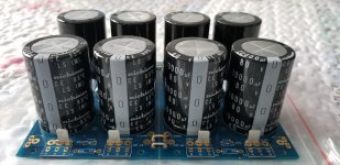
The recommended 40.000uF pr rail is for 2ch. So you got more then enough.
Your capacitors voltage rating depends on your transformer. I run 2x40V transformer with 63V caps. And i would skip the CRC resistors in the PSU when used with a class A/B amp.
Your capacitors voltage rating depends on your transformer. I run 2x40V transformer with 63V caps. And i would skip the CRC resistors in the PSU when used with a class A/B amp.
Then i would go for the 80V caps. But you should only run the amp with 8ohm speakers at that voltage.
My transformer will be a 45-0-45 center tapped toroidal.
For what its worth, I used this... My speakers were going to be an easy to drive 6R speaker.
Attachments
Yesterday, i realy pushed my amp to the limit. funny fact. my UcD400HG driving the 2x15" subs was doing just fine untill i turned up the volume. the hypex started clipping 2x ST PSU, and 2x 500VA transformers. The funy fact is: prior to the hypex beeing build. the 5ch honeybader was driving the subs. AND front speakers. and it never cliped. it drove the system to about 6db more alone, then what the hypex could do 😛
you can push your amp to clipping, but you can never get it to put out the same power that is was designed for using sine waves...listening to music....
Tony. True. And i belive it was the PSU that strangled the UcD amp. They was bought supplyed by 1000VA 2x40V transformers.
BTW: the UcD400 clipped HARD.
It is still funny that my HB could play a lot louder given the same same voltage and transformer VA. and it drove the front speakers at the same time 🙂
it must be PSU delivery of current.
BTW: the UcD400 clipped HARD.
It is still funny that my HB could play a lot louder given the same same voltage and transformer VA. and it drove the front speakers at the same time 🙂
it must be PSU delivery of current.
Last edited:
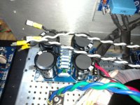
big traffos and huge reservoirs, they helped the amp a lot when things get rough...low voltage sags and low ripples.....good thing....
Last edited:
yes they do 🙂 so hypex rec 6.800uF pr amp ( UcD400) seems a little low 😛
give it 100.000uF and some caps that can deliver current.
give it 100.000uF and some caps that can deliver current.
Last edited:
I'm glad that i overbuild the HB amp PSU. 180.000uF PSU on a 5ch amp. The back ch will nok take much. oh hell what a current drive for the fronts 🙂
Getting the Badger in shape....
I'm sure all you master build types already do this, but when I was mounting the fuse holders, I was wondering if the spacing would be correct... several wast to go about it, but I like it simple. I grabbed the fuse I will use and snapped it in to the two holders, gave it just a bit extra room and then set the fuse and holder package in place; solder from the top with anything to hold it in place. That's another thing I learned in this journey.... Faston or TP, if there is room, just tack them from the top, so you are assured of getting them plumb. 😉
I'm sure all you master build types already do this, but when I was mounting the fuse holders, I was wondering if the spacing would be correct... several wast to go about it, but I like it simple. I grabbed the fuse I will use and snapped it in to the two holders, gave it just a bit extra room and then set the fuse and holder package in place; solder from the top with anything to hold it in place. That's another thing I learned in this journey.... Faston or TP, if there is room, just tack them from the top, so you are assured of getting them plumb. 😉
Attachments
Last edited:
That's the way to do it of course. A long time ago I worked for a manufacturer that was using a purchased power supply on a product. We started getting returns with the power supply fuse blown. There was no sign of overload and all the supplies worked when the fuses were replaced. I ended up visiting the supply vendor and watched them assemble the supply, I noticed that the workers had to press some of the fuses in very hard.. It turned out that they just pressed the clips in and wave soldered the boards, and the alignment was basically random. I told them to put the fuse in before soldering, Viola problem solved.
Uh oh...
Not knowing this when I built my Badger, I populated R1-5 on the DIYStore PS boards...it's been running for almost a year now, but should I remove these resistors? Could this R in the PS manifest as compressed dynamics at higher volume?
All in all, for my first amp build, it exceeds all expectations! Combing the threads for all part values/substitutions/choices was a chore, but when it didn't blow up (and sounded better than the Parasound it replaced)...worth EVERY minute!!
Thanks OS/diyaudio
Not knowing this when I built my Badger, I populated R1-5 on the DIYStore PS boards...it's been running for almost a year now, but should I remove these resistors? Could this R in the PS manifest as compressed dynamics at higher volume?
Yep. No CLC or CRC since the current is not constant as with a Class-A. The variable current of an AB amp would cause a variable voltage drop across the R (or L), thus modulating the rail voltage with the audio signal.
All in all, for my first amp build, it exceeds all expectations! Combing the threads for all part values/substitutions/choices was a chore, but when it didn't blow up (and sounded better than the Parasound it replaced)...worth EVERY minute!!
Thanks OS/diyaudio
Attachments

Uh oh...
Shoot...so I shouldn't have populated R1-5 on my universal PS boards from the store? Would that cause what I can only describe as compressed dynamics at higher volume? My Badger has been running for almost a year (and sounding better than the Parasound HCA it replaced) with these resistors in place.
Hats off to OS and diyaudio for sharing this circuit! Was a bit intimidated as this was my first amp build, but worth every second when it didn't blow up and brought musicians into my living room😀
Yep. No CLC or CRC since the current is not constant as with a Class-A. The variable current of an AB amp would cause a variable voltage drop across the R (or L), thus modulating the rail voltage with the audio signal.
Shoot...so I shouldn't have populated R1-5 on my universal PS boards from the store? Would that cause what I can only describe as compressed dynamics at higher volume? My Badger has been running for almost a year (and sounding better than the Parasound HCA it replaced) with these resistors in place.
Hats off to OS and diyaudio for sharing this circuit! Was a bit intimidated as this was my first amp build, but worth every second when it didn't blow up and brought musicians into my living room😀
Attachments

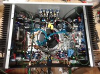
And that's it my boards are complete.
Just need to install the transistors and stand offs on the heatsinks.
Sent from my SM-G920I using Tapatalk
Link to coil findings
Thanks for this Stuart, I'm at this point now and wanted to verify. This is perfect, I'm going to use your results to check my own.... A belated thanks!
JT
Last edited:
Not knowing this when I built my Badger, I populated R1-5 on the DIYStore PS boards...it's been running for almost a year now, but should I remove these resistors? Could this R in the PS manifest as compressed dynamics at higher volume.CRC power supply is designed to reduce ripple. If you don't need that, go ahead and jump across your resistors. Either way, you are unlikely to hear a difference. The Badger has good PSRR.
Yep. No CLC or CRC since the current is not constant as with a Class-A. The variable current of an AB amp would cause a variable voltage drop across the R (or L), thus modulating the rail voltage with the audio signal.
Hi All,
I don't want to upset anyone nor do I want miss information passed on as being correct and other members following it who may not know any better at this time.
I do no agree with the statements made in post 4419.
I would not be modifying the CLC or CRC network on the diy power supply for fear of "modulating the rail voltage with the audio signal"
Yes the rail voltage may vary a little as the current through them changes but this will not have an effect of changing quality of the output signal.
Those networks are there to reduce noise and 60hz Hum. So removing them will increase overall THD and THD+N
Last edited:
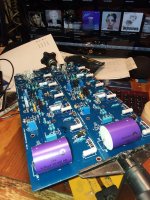
Yes, my CRC PS as shown in the attachment works very well with HB. I do not remember what resistor values I finally used but that's fine tuning. I have also a complementary RC (100nF + 1ohm) circuit added at the voltage input to each pcb.
I'd like to add that DigiKey still has low noise transistors from Central. These are 2n5087 and 2n5210. Max noise at 1kHz, Ic=100uA Vce=-5V is 2dB. At least that's what datasheet says and some guys who used these transistors. I've just purchased these and will use these in future HB and other projects. Hopefully I'll be happy with them. So far I used 2sc2240 / 2sa970 high voltage low noise transistors and they are really fine but difficult to get except for Chinese clones, some of which are apparently not worse when it comes to noise performance.
cheers,
Attachments
Yep. No CLC or CRC since the current is not constant as with a Class-A. The variable current of an AB amp would cause a variable voltage drop across the R (or L), thus modulating the rail voltage with the audio signal.
i do not see this as untrue...class A amps as in Nelson Pass amps used this arrangement, for class AB i see no point...
for class AB, the idle current can be a few mA to several amperes of current that flows thru those resistors so there will be a hit somehow...
Last edited:
- Home
- Amplifiers
- Solid State
- diyAB Amp The "Honey Badger" build thread