Yes, but it was mains fuse which was underrated. PS fuses were not affected. Maybe it blew because it was underrated. Nevertheless, the main question is what caused that oscillation. Without the input shortened hum is about a few hundred uA and it's only hum.
cheers,
cheers,
Ostripper and JojoD wrote very good build guides, if you followed them to letter, then the amp should work the first time...
I followed JojoD build guide to the letter, measured each component and matched for left and right channel boards. Light bulb & soft start today.
Ron
"The best laid plans.........." , 1/2 way through I ran out of thermal paste. Figures.....
Pictures tomorrow.
Ron
Pictures tomorrow.
Ron
Finished populating my boards today. I checked everything twice, at least.
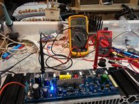
I used the light bulb in series to start it up with the 10 Ohm 1 Watt resistors in the fuse holders. Slow start circuit before the TX. Light bulb lit dimly and then almost went out.
Voltage across the fuse peaked ~.31 Volts then dropped down to .12 V. Offset was at .02mV before I adjusted it to .00mV. It stayed there and never moved. 🙂 I adjusted the Bias to .15mV and let it sit there for ~ 30 minutes. Turned it off and removed the light bulb, replaced the R's with fuses and turned the power back on. To my surprise the Bias was now ~.38mV. I quickly turned down the bias and adjusted it to .30mV and let it warm up. It took about an hour to stabilize the heat sink temperature. It barely got warm, maybe 90*F.
Note; notice the tape on the tips of the test probes to prevent them from slipping through the holes and shorting out on the Heat sink. Just a tip.
I'm so happy!
OK folks, if a dumb solder monkey like me can build these boards and get them working on the first try then anybody can. If you are waiting or sitting on the fence about building this amp, Just do it!
Thank you OS for sharing this with us. I can't wait to power up my good speakers and hear how great this amp sounds.
Thank you!
Ron
Attachments
Last edited:
Ho Ron,Finished populating my boards today. I checked everything twice, at least.
I used the light bulb in series to start it up with the 10 Ohm 1 Watt resistors in the fuse holders. Slow start circuit before the TX. Light bulb lit dimly and then almost went out.
Voltage across the fuse peaked ~.31 Volts then dropped down to .12 V. Offset was at .02mV before I adjusted it to .00mV. It stayed there and never moved. 🙂 I adjusted the Bias to .15mV and let it sit there for ~ 30 minutes. Turned it off and removed the light bulb, replaced the R's with fuses and turned the power back on. To my surprise the Bias was now ~.38mV. I quickly turned down the bias and adjusted it to .30mV and let it warm up. It took about an hour to stabilize the heat sink temperature. It barely got warm, maybe 90*F.
Note; notice the tape on the tips of the test probes to prevent them from slipping through the holes and shorting out on the Heat sink. Just a tip.
I'm so happy!
OK folks, if a dumb solder monkey like me can build these boards and get them working on the first try then anybody can. If you are waiting or sitting on the fence about building this amp, Just do it!
Thank you OS for sharing this with us. I can't wait to power up my good speakers and hear how great this amp sounds.
Thank you!
Ron
Congratulations on your succesful build!
Looking past the "I built it myself"-bias, how does it sound? Does it do what you want it to? Can you try to describe the sound? What speakers do you drive with it?
Do you think it will be helpful or necessary to have an oscilloscope and function-generator for setting-up and testing?
Thanks,
James.
JB,
I only tested the individual boards mounted on the heatsink. I have not yet finished building the amplifier. (Honey Do Lists) (Wife want things done first).
At this point I am not able to describe the sound of this Amplifier. I have a Pass F5 that I built and am currently using with a pair of Small Thor's which are extremely revealing.
I don't think either a O'scope or function generator is required once the amp is built.
Others with much greater knowledge (just about everyone) have examined this amplifier and offered their ideas and opinions during the design phase, I see no reason to doubt the final product is a finished and competent design.
When completed and I trust what I have built , I will do a direct comparison of the two Amps. My F5 is built with quality parts and is dead silent, extremely transparent musicaly but lacks the punch and snap (PRAT?) to drive my Thors. I am sure the Honey Badger will have plenty of headroom.
Ron
Generator and scope may be useful if there is a problem, but if you have been careful assembling the boards using recommended components you shouldn't have any issues. They are necessary in the development stage, but Ostripper has taken care of that for us.
The only close comparison I have done was against a Leach amp build on Jens Rasmussen's 5 output pair boards. Both amps used MJL0281/0302 outputs biased similarly (around 50 mA each IIRC). The input differential on the HB is MPSA-18s and the Leach inputs are BC546/556. The Honey Badger cascode is zener referenced. Speakers are a Zaph design using W15CY001 and T25CF001. I use an OPPO BDP-103 to drive the HB directly.
The HB seems to reveal a bit more low level detail. You might consider it a ringing endorsement that once in my main system it has remained for the past 18 months. I hope to have a couple more amps to compare to shortly, Pass AJ and F5T, but these projects have been almost complete for a while. No burning issues to push me to finish...
Will do!...
Try the 22K and see how the brightness suits.
Currently cutting costs off of my BOM, by finding different suppliers.
It may become feasable yet..!
@BobEllis: sounds good! Hope to get my price down just a little more, so I can actually make this happen!
Cheers!
Last edited:
Glad to hear you are finding less expensive suppliers for your needed parts.
Keep going!
Thanks Bob, appreciate your continued expertise in this (and other) threads..
Ron
Keep going!
Thanks Bob, appreciate your continued expertise in this (and other) threads..
Ron
Almost done!
Hey friends,
Question, on the input signal wire inside the chassis, I'm using Canare 2T2S, which has 2 conductors and is shielded, should I connect the shield / drain to the chassis or let it "float"? My RCA jacks are NOT electrically connected to the chassis.
Thanks,
Ron
Hey friends,
Question, on the input signal wire inside the chassis, I'm using Canare 2T2S, which has 2 conductors and is shielded, should I connect the shield / drain to the chassis or let it "float"? My RCA jacks are NOT electrically connected to the chassis.
Thanks,
Ron
HB noise
Seems that noise problem is fixed but I do not know whether permanently or not as it's not easy to find a source of some intermittent problem.
I started at the beginning so I removed the input cap: a large polypropylene 5.6uF cap. De-soldered it to find out that it measured perfectly well. I soldered wire in it's place and all noise was gone completely but offset jumped to 70mV which was understandable. I did not try to correct it as I would not use the amp without some input cap. So I soldered in a 4.7uF Nautilus audio cap on the other side of the board as its wires are thick copper. Apparently these are good audio caps. I have four of these but never tried one before. Most importantly it was smaller and although noise returned it was at lower level measurably and audibly. Looks caps ain't caps.
Next I decided, just in case, to replace the input pair with the same ss9014 transistors but with lower Hfe so C replaced D and I increased caps on the Toshiba drivers from 33pF to 47pF. It did not change noise level but removing input shortening plug became much less audible. All that outside the box with bench PS with only +/-37.4V.
Next I decided to screen the soldering part of the board as touching input ground on the board or the input cap kept removing noise. Even pcb screen with thin copper worked. It did not remove noise but reduced it substantially. So that was it, hopefully. As a final touch I increased bias from 60mA to 80mA for +/-64V PS and put everything into the amp's case.
After running it for two days I think I'll reduce bias to about 70mA and make some screens and will screen toroid with a soft steel band.
Renron,
I use Canare cables as well both two and four active wires. Solder screen to the ground on one side of the plug and mark it. The other side is floated.
cheers,
Last edited:
You should spray some freeze spray on each of the semi's. Noise ,
or a sudden increase of it , is a sign of a bad semi junction 😱 .
If this just "came out of the blue" , you might want to crosscheck
the noisy side with the good side.
Sometimes this will not work , as the noisy junction will exhibit the
same static electrical characteristics as a good one would.
PS - I've had "noisy ones" on OEM repairs - spray (cool it down) ....
the noise disappears or changes.
OS
Hey friends,
Question, on the input signal wire inside the chassis, I'm using Canare 2T2S, which has 2 conductors and is shielded, should I connect the shield / drain to the chassis or let it "float"? My RCA jacks are NOT electrically connected to the chassis.
Thanks,
Ron
You want the shield at the Badgers "lifted ground" potential.
since there are 2 wires inside , and you already have input ground/input
connected .... try chassis earth and/or the lifted ground connection
for the least hum.
On my amp (2 wires + shield) , I have 1 wire + shield connected to
the "lifted ground" and the other to the actual input - silent !
It's a waste to let it "float" .
OS
AJT, JANUSZ, OS,
Thank you for answering my question, from my "interwebs" reading, I thought this was the preferred method. But it's assuring to have it answered by people I trust.
Ron
Thank you for answering my question, from my "interwebs" reading, I thought this was the preferred method. But it's assuring to have it answered by people I trust.
Ron
You should spray some freeze spray on each of the semi's. Noise ,
or a sudden increase of it , is a sign of a bad semi junction 😱 .
If this just "came out of the blue" , you might want to crosscheck
the noisy side with the good side.
Sometimes this will not work , as the noisy junction will exhibit the
same static electrical characteristics as a good one would.
PS - I've had "noisy ones" on OEM repairs - spray (cool it down) ....
the noise disappears or changes.
OS
Thanks OS,
intermitent noise came out of the blue a couple of times for a number of seconds after almost a year of operation and after a couple of weeks mains fuse blew but it was seriously underrated and soft start was disconnected. Noise is gone now but I'm afraid it might return.
Apart doing the above I also resoldered most transistor joints but not all as actually all joints looked good. I'll resolder all of them just in case as you have suggested bad joint somewhere. Both boards out of the case measure the same, zoebel stays cold with input shortened and noise on. My case is so tight I have to take modules out of it to do anything with them.
Could you explain in more detail how you solder and use your cables? Maybe a drawing? Not all equipment has floated ground. I made some cables with screen solderd to ground on one side and some with screen solederd to ground on both sides.
cheers,
Last edited:
Thanks OS,
intermitent noise came out of the blue a couple of times for a number of seconds after almost a year of operation and after a couple of weeks mains fuse blew but it was seriously underrated and soft start was disconnected. Noise is gone now but I'm afraid it might return.
Apart doing the above I also resoldered most transistor joints but not all as actually all joints looked good. I'll resolder all of them just in case as you have suggested bad joint somewhere. Both boards out of the case measure the same, zoebel stays cold with input shortened and noise on. My case is so tight I have to take modules out of it to do anything with them.
Could you explain in more detail how you solder and use your cables? Maybe a drawing? Not all equipment has floated ground. I made some cables with screen solderd to ground on one side and some with screen solederd to ground on both sides.
cheers,
By "junctions" I meant the actual transistors themselves , not the solder joints. (but these also could cause noise).
The freeze spray will thermally contract both solder joints and semiconductor
junctions. Most electronic distributors carry some.
OS
I'll get freeze spray and will try it.
When it comes to cabling I thought Renron asked about interconnecting cables and these should have screen connected to ground wire and plug ground on one side. The other is floated. I made two cables with screen soldered on both sides to the ground wire (and plug case) to find out differences could be heard but I could not hear any difference.
cheers,
- Home
- Amplifiers
- Solid State
- diyAB Amp The "Honey Badger" build thread