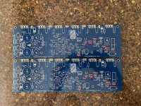
Is anybody else having issues with the via size for the 1/4 watt resistors on these boards? On the boards I received, none of the vias for 1/4 watt resistors left of R6 are large enough for any resistor I have tried (the right via for R6 was also too small). I tried reaming them out with a thumbtack without success (used enough pressure to break the thumbtack). Since the issue is identical on each board it seems it is not a defect with the board but due to the design? 😕
Attachments
Hi wdavis009,
Yes, the diameters of the holes are a problem. The solution is an easy one : I did use a drill bit in order to get larger diameter holes. This has been only slowly hand done ! So I have had no problem with the PCBs and could place the resistors I had around. It takes time and it is painful for the fingers 🙄 ...
Best regards
rephil
Three amp builders have issues with a small oscillation at start up and sometimes when playing music after a while.
We believe that the oscillation originates from the bases of Q3, Q4, C6 and Zener.
DIYAudio member Gareth removed C6 and the oscillation disappeared.
Stuart (who had the same problem) and I decided to experiment further.
The third amp builder had the same issue but did not initially realise it was there.
I remembered a lecturer many, many years ago emphasizing that a zener diode needs enough current to operate correctly i.e. gets past the “knee” curve.
In summary (this was a very long process) these are the steps that Stuart performed on his amp and the results obtained:
1. Replaced the 15V 1.2Watt zener for a 15V 0.5Watt zener for less minimum current requirement. (Schematic shows 12V 0.4watt). Oscillation was reduced but still there.
2. Removed C6. No oscillation. Confirmed Gareth’s findings.
3. The "correct" resistor value for the zener was worked out for 64V rails but R19 was only reduced from 68K to 15K to see if we were heading in the right direction. C6 was re installed. Amp was run for 3 days on music, sine and square waves. No oscillation.
4. THD was compared from before the modification to after modification and the distortion had decreased slightly by lowering the value of R19.
So to understand if indeed we are heading in the right direction, how did OS work out the value for R19?
What is the frequency of oscillation? Try splicing a resistor into the trace that feeds the Q3 and Q4 bases, since removing C6 worked. You may start at 22k and then see if 1k works, then 100ohm and so on to find the minimum value needed.
Bonsai has documented an LTP cascode oscillation in one of his amps, I think it was 180MHz.
Is anybody else having issues with the via size for the 1/4 watt resistors on these boards? On the boards I received, none of the vias for 1/4 watt resistors left of R6 are large enough for any resistor I have tried (the right via for R6 was also too small). I tried reaming them out with a thumbtack without success (used enough pressure to break the thumbtack). Since the issue is identical on each board it seems it is not a defect with the board but due to the design? 😕
They are a little small. you can use resistors with a lead diameter of up to 0.55mm. Most 0.6W resistors have lead diameter of 0.6mm. But som are 0.55mm.
For those who haven't ordered parts yet:
(1) Dale CMF55 and RN55 are .64, Takman are .6, and PRP are .6 and don't work without enlarging the via size.
(2) Yaego, Xicon, and TE (R8 only) are .55 or smaller, as well as Dale CMF50 and RN50 (1/8 watt) and should work (though I don't have/use any of these so can't confirm).
(1) Dale CMF55 and RN55 are .64, Takman are .6, and PRP are .6 and don't work without enlarging the via size.
(2) Yaego, Xicon, and TE (R8 only) are .55 or smaller, as well as Dale CMF50 and RN50 (1/8 watt) and should work (though I don't have/use any of these so can't confirm).
What is the frequency of oscillation? Try splicing a resistor into the trace that feeds the Q3 and Q4 bases, since removing C6 worked. You may start at 22k and then see if 1k works, then 100ohm and so on to find the minimum value needed.
Bonsai has documented an LTP cascode oscillation in one of his amps, I think it was 180MHz.
What schematic you looking?
Is anybody else having issues with the via size for the 1/4 watt resistors on these boards? On the boards I received, none of the vias for 1/4 watt resistors left of R6 are large enough for any resistor I have tried (the right via for R6 was also too small). I tried reaming them out with a thumbtack without success (used enough pressure to break the thumbtack). Since the issue is identical on each board it seems it is not a defect with the board but due to the design? 😕
the solder pads and traces are big enough, so that even if i can not push the leads in, soldering the leads on the pads itself is okey...
otoh, you can use a 1 mm bit, but then you may have to solder on both sides of the board..
the bases of Q3/Q4 are at ac zero, being a common base ckt, adding a C6 cap there created a low frequency zero, so that phase shifts with frequency and the type of cap used caused instability...
http://cdn.shopify.com/s/files/1/1006/5046/products/badger_v2.4_1024x1024.gifWhat schematic you looking?

how come the end of the 22k also connected to ground? or am i seeing it wrong?
We are not talking about using the resistor option.
Check the build guide.
We are talking about using the zener option. When the zener option is used the 22k resistor is not used and a jumper is soldered in on the pcb. See attached photo.
With the zener option. The Anode goes to signal ground.
With the resistor option the 22k R18 resistor goes to the intersection of R15 & R16 as you can see on the schematic.
But once again we are not talking about the resistor option using R18.

okey, i still think that it should be made clear even from the schematics....a footnote or something..
Is anybody else having issues with the via size for the 1/4 watt resistors on these boards?
You can purchase these off ebay.
PCB Print Circuit 10Pcs 0.6-1.5mm CNC Board Carbide Mini Micro Drill Bits SS0595 732040972633 | eBay
I just use them by hand stepping up one size at a time until the component fits.

Once again we are talking about who can make changes or add notes to the schematic and reference them in the build guide etc. It seams that its basically impossible to get and suggestions or foot notes added to the documentation to prevent other members from having simlar problems.okey, i still think that it should be made clear even from the schematics....a footnote or something..
To stop any confusion (Tony) even though I made it clear in my original post that I was discussing the ZENER current - see simplified schematic attached for reference.
Hi Guys
I ask again - how do you think that OS obtain a value of 68K? Please no off topic answers.
Hi Keantoken
many thanks for your response. I believe that Stuart has sent you a photo of the oscillation/ noise.
Hi Guys
I ask again - how do you think that OS obtain a value of 68K? Please no off topic answers.
Hi Keantoken
many thanks for your response. I believe that Stuart has sent you a photo of the oscillation/ noise.
Attachments

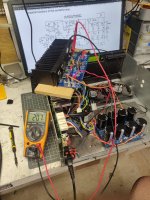
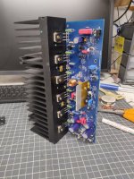
So I'm firing up one channel of the badger. Bias is set and steady at 20.7mv. offset is steady at 1.3mv. heatsink is warm, not hot. 3.5ma across r14 for tail current. That is also showing 7.75v. I will have to make sure I get those fans wired up to run when the amp is running.
Attachments
Last edited:
How do you think that OS obtain a value of 68K?
Hi Harry, As it is unlikely that OS will chime in on this. One theory is that the circuit was designed first with the resistor option, so R19 and R18 were sized according to set the base voltage of the cascode to around 15v.
Then the zener option was added and R19 was not sized to suit the minimum current requirements of the zener diode to ensure that it operates in the negitive breakdown region to maintain its steady voltage.
It may not have been a problem for OS as the schematic calls for a 1/4watt zener part number BZX84C15L. I believe that this zener is now not available in a through hole or is obsolete.
From what I have read it appears that you need approximately 10% of the maximum allowable current flowing through the zener to ensure that it operates correctly in the negitive breakdown region to maintain a steady voltage.
So for the 1/4watt 15v zener that's ~1.7mA. Based on 64v rails and R19 being 68K this gives us about 700uA so still lower than the minimum but it must have been ok.
I initially used the zener diode listed on the BOM its part number was 1N4744AVSCT-ND this was a 1.3 watt
This would have required at least 8.7mA far about the 700uA set by R19 at 68K.
I ended up ordering some 0.5w 15V and 12V zeners from digikey part number BZX55B12-TAPGICT-ND
This lowered the required current to 4.1mA. I then replaced R19 with a 15K 0.5watt metal film resistor mounted to the underside of the pcb away from either of the two cascode transistors.
This gave me ~3.5mA through the zener which was lower then the minimum requirements. But it was a starting point and I wanted to keep the heat dissipation down.
I have not experienced and random oscillation or noise since.
Are there any other theories as to how OS obtain a value of 68K?
Last edited:
Hi wdavis009,
Yes, the diameters of the holes are a problem. The solution is an easy one : I did use a drill bit in order to get larger diameter holes. This has been only slowly hand done ! So I have had no problem with the PCBs and could place the resistors I had around. It takes time and it is painful for the fingers 🙄 ...
Best regards
rephil
I found out much the same. I have a miniature drill bit set with a handle for the tiny bits I used. Did not take that much time to do but was another step that had to be taken. Amazon search for miniature or minture drill bit set or either google will give you results.
- Home
- Amplifiers
- Solid State
- diyAB Amp The "Honey Badger" build thread