Given you have the emitter follower - common-emitter VAS, don't bother cascoding, it buys you very little.
For current limiting, what you added is what I had in mind.
Thanks Sandrohv,
Making progress. I want to test the boards before I add the output devices. I have attached a marked up schematic. I want to run a couple of resistors off the drivers output and return a nfb signal to the board. Is tthe attached schematic correct? What about the 150R r36 and cap 26? Do I need to pull them? Or just the resistor? Cheers guys.
Attachments
when i test an amp, i do it with all the parts in, check and double check parts placements..then when powering up, i install a series lamp tester...i never lost parts this way....then when the series lamp brigthen and then dimmed you have a viable amp..
time to check the output offset voltage, +-100mV is acceptable, but closer to zero volts is desired...
having done this output offset voltage check, you can then proceed to adjust bias, take note that the series lamp bulb might glow a bit more....
you can power down, remove the series lamp tester and then you can use your amp of repeat output offset voltage tests and idle bias adjustments..
if you have a scope, with a 8 ohm dummy load and 2.8 vac at output, you need a 1khz sine wave source, check for zero crossover distortion, adjust if needed until you see a smooth transition at the zero crossing...
you can adjust for the smallest idle current that does not give you crossover distortion..
Yes, higher (possibly regulated) voltage on the input and VAS certainly has merits and it's not difficult to implement although somewhat more expensive.
I got Stochino. Fast amps sound better. I remember when in 1980s Electrocompaniet introduced its 100V/us amp. Even half deaf could hear the difference as amps of that time rarely had SR higher than 20V/us. A friend of mine has among other stuff the whole Electrocompaniet system from sources to the power amp plug into electrostats. Very clean and balanced sound.
cheers,
where is the like button.....? yes i agree...
So I hooked up one channel last night, using a dim bulb tester, then with a higher wattage bulb, and then direct ac, and no smoke, so that is good. DC offset about 9mv. But... When I fed a 1000hz signal into the board, and checked the output on a scope, I saw that the output was riding on a large sine wave. I found the same wave to be present if I checked the signal at the case. (no 1000hz wave). I then disconnected the power supply from the transformer, and sine wave still present. Reading about 1.1vac. Rail voltages are steady and even at about 64V.
Gotta be a psu grounding issue right? I am using a monolithic bridge rectifier mounted directly on an aluminum chassis that is bolted to the case. The center tap wires (2) from the transformer are going to the PSU ground same side as +- from rectifier. Does this need to be isolated with an insulator? Other question is, does the ground from the capacitor board need to be connected to the chassis? Clean or dirty side? Doesn't matter because they are one ground...? The iec plug at the rear of the unit only has two prongs. The ac is present at lower voltages when connected directly to the wall. Maybe the huge transformer doesn't like being connected to a power strip that is connected to another power strip with like 10 other things on it.... lol.
Gotta be a psu grounding issue right? I am using a monolithic bridge rectifier mounted directly on an aluminum chassis that is bolted to the case. The center tap wires (2) from the transformer are going to the PSU ground same side as +- from rectifier. Does this need to be isolated with an insulator? Other question is, does the ground from the capacitor board need to be connected to the chassis? Clean or dirty side? Doesn't matter because they are one ground...? The iec plug at the rear of the unit only has two prongs. The ac is present at lower voltages when connected directly to the wall. Maybe the huge transformer doesn't like being connected to a power strip that is connected to another power strip with like 10 other things on it.... lol.
Is the spurious ac signal line frequency, or a harmonic?
The fastest way to tell is to switch the scope trigger to line and see if the waveform stands still.
tommost
The fastest way to tell is to switch the scope trigger to line and see if the waveform stands still.
tommost
Yeah, it stands still. present with amplifier board removed. Also present with rectifier and power supply caps removed. I have two additional toroidal transformer installed, one is the standby, and is required to power up the relays to connect the main transformer, and the accessories transformer (+-15v, etc... not currently used for anything). all three transformers have a ground line that goes to a common chassis point near the main transformer.
Edit:
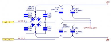
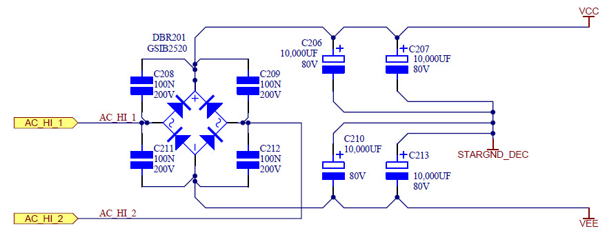
Maybe because there are two secondaries on the main transformer, I should only be running one of the center tap wires to the PSU ground. It would make sense that one center tap wire is for the high voltage secondaries, and the other for the lower voltage secondaries. So should I just be using the one for the High volt? Looking at the schematic for the arcam, I should probably be running the center tap wire to straight to the star ground side of the PSU cap board.
I have attached a schematic of the main psu diagram. I am not using c208, 209, 211, and 212.
Edit:
Maybe because there are two secondaries on the main transformer, I should only be running one of the center tap wires to the PSU ground. It would make sense that one center tap wire is for the high voltage secondaries, and the other for the lower voltage secondaries. So should I just be using the one for the High volt? Looking at the schematic for the arcam, I should probably be running the center tap wire to straight to the star ground side of the PSU cap board.
I have attached a schematic of the main psu diagram. I am not using c208, 209, 211, and 212.
Attachments

Last edited:
The center tap is not two separate center taps. They both tie into the high volt. Guess one center tap is needed for multiple secondaries. Makes sense. Sorry for multiple posts. Tried to edit, but option disappeared. I bet I need to run a ground wire from the soft start board to the star ground.
Last edited:
Postmaster. Here is a pic of the wave I see at the case, or pretty much anywhere I else I poke around with the probe. I grounded the power supply soft start control board per the star ground in the arcam schematic I posted earlier. But a big high voltage sine wave like this isn't acceptable. Scope was on the highest voltage setting with the probe on x1. 5 volt scale on the scope. My noobness may be showing. I'm going to search psu issue threads. It's coming from the standby transformer, as with everything else unplugged, I still see the voltage. Thanks for bearing with me.
with power off and scope connected, move your power traffo around and see if it helps...
find the orientation where the noise is nulled..
find the orientation where the noise is nulled..
you need equalizing resistors across the caps...so that even if you forgot to connect the power traffo center tap, your amp still works because of the virtual ground that is created..
Last edited:
Oscillation
Three amp builders have issues with a small oscillation at start up and sometimes when playing music after a while.
We believe that the oscillation originates from the bases of Q3, Q4, C6 and Zener.
DIYAudio member Gareth removed C6 and the oscillation disappeared.
Stuart (who had the same problem) and I decided to experiment further.
The third amp builder had the same issue but did not initially realise it was there.
I remembered a lecturer many, many years ago emphasizing that a zener diode needs enough current to operate correctly i.e. gets past the “knee” curve.
In summary (this was a very long process) these are the steps that Stuart performed on his amp and the results obtained:
1. Replaced the 15V 1.2Watt zener for a 15V 0.5Watt zener for less minimum current requirement. (Schematic shows 12V 0.4watt). Oscillation was reduced but still there.
2. Removed C6. No oscillation. Confirmed Gareth’s findings.
3. The "correct" resistor value for the zener was worked out for 64V rails but R19 was only reduced from 68K to 15K to see if we were heading in the right direction. C6 was re installed. Amp was run for 3 days on music, sine and square waves. No oscillation.
4. THD was compared from before the modification to after modification and the distortion had decreased slightly by lowering the value of R19.
So to understand if indeed we are heading in the right direction, how did OS work out the value for R19?
R19? that was a mere voltage divider designed to give the input ltp a certain collector voltage, the cascode Q3/4 bases are then effectively at ac ground with the R19//R18//C22...that is 68k//22k/Xc22ufd...
so the answer to how he arrived at R19? by assuming the Q3/4 have very high hFE...
he wanted a collector voltage for Q1/2 of Vcc x 22k/88k or 65*[22/88] or 16.5 volts dc..
isn't it obvious? that he selected zener of 15 volts?
you are correct to think that perhaps the 68k can be say 47k when using 15v zeners..
if you put in zeners instead of a resistor, then just use the zener bypassed with 22ufd ecap..
you are correct to think that perhaps the 68k can be say 47k when using 15v zeners..
if you put in zeners instead of a resistor, then just use the zener bypassed with 22ufd ecap..
Some interesting reading about the selection of R19
AN008 - How to Use Zener Diodes
AN007 - High Power Zener Diode
After 5 weeks of carefully trying one thing at a time and checking the results of the first 20 seconds on my scope. It was clear that reducing the value of R19 was the solution.
I ended up going with a 15k one watt resistor which is about 10% of the maximum current the zener can handle assuming 64 volt rails.
I also mounted the resistors under the pcb away from either of the two cascode transistors.
I used one watt because the heat dissipation was about 180-230mw depending on if you used a 15v or 12v zener
Last edited:
Hi Tony,
I think you're referring to the voltage divider option as there is no R18 in the zener option circuit.
The zener derives it's current through R19.
I think you're referring to the voltage divider option as there is no R18 in the zener option circuit.
The zener derives it's current through R19.
Hi Tony,
I think you're referring to the voltage divider option as there is no R18 in the zener option circuit.
The zener derives it's current through R19.
yes, it is either or...
I ran the resistor option with and without C6 and there was no problem.yes, it is resistors only option...
So if other members choose the resistor option then there should be no problem following the 2.4 Schematic.
However if a member chooses to use the zener option then its probably a good idea to lower R19 as currently the current through the zener D3 is only about 640uA (depending on rail voltages) which is to low for the zener to operate correctly in the negitive breakdown region.
Yeah, it stands still. present with amplifier board removed. Also present with rectifier and power supply caps removed. I have two additional toroidal transformer installed, one is the standby, and is required to power up the relays to connect the main transformer, and the accessories transformer (+-15v, etc... not currently used for anything). all three transformers have a ground line that goes to a common chassis point near the main transformer.
Edit:
Maybe because there are two secondaries on the main transformer, I should only be running one of the center tap wires to the PSU ground. It would make sense that one center tap wire is for the high voltage secondaries, and the other for the lower voltage secondaries. So should I just be using the one for the High volt? Looking at the schematic for the arcam, I should probably be running the center tap wire to straight to the star ground side of the PSU cap board.
I have attached a schematic of the main psu diagram. I am not using c208, 209, 211, and 212.
Why don't you use two bridges - one for each secondary wiring? It has more merits than the single one. The only price is about 1V drop.
cheers,
Attachments
- Home
- Amplifiers
- Solid State
- diyAB Amp The "Honey Badger" build thread