The Honey Badger BOM specifies Nobel-brand resistors for R43 to R48, the 0.22R power resistors. In Post #42, Danielwritesback posted a BOM with a link to a vendor for these, Analog Metric, in Hong Kong. Analog Metric no longer sells these. An e-mail asking about them got the response “We have KOA 0.22R 5W in stock. Please advise if this is ok.” A visit to KOA’s web sited showed that KOA Speer doesn’t have a suitable replacement for the Nobel RGC3 or RGC5.
Unfortunately, the pads for these resistors are too close together to accommodate any other resistor I’ve found. Of course, conventional wirewound resistors can be used, standing them up on end, but I’d rather have the Nobel resistors.
Nobel’s web site http://www.nobleusa.com/pdf/rgb-rgg.pdf has the resistors, and a list of distributors, but so far none that I’ve contacted have responded to my e-mail asking for a quote for 25 of them. I think these distributors are set up to sell to manufacturers who buy thousands at a time.
So the question is: Has anyone found either a replacement for the Nobel resistors for R43 to R48, or a source for the Nobel brand?
I have found the following at AnalogMetric:
Cement 0.2 Ohm 5W Non-inductance Resistor_Cement_Resistor_Analog Metric - DIY Audio Kit
Seem to be a fair replacement for the specified Nobel resistor and have about the right pinout. Hopefully the quality is good. There was one possibility on ebay that I found, but I've gone for the units above myself.
Building an amplifier seems like madness at the moment, but what can possibly go wrong? 🙂
Success!
I can't believe I first posted that I "took the plunge" back on February 22. What can I say? I'm a busy guy. I'm listening to one channel right now, using a power supply taken from another build. So far, it sounds good in mono. The second channel should go much faster!
Thank you, Wembley, for the link. I bought 4 boards. So maybe I'll use the resistors from Analog Metric for the second pair.
I'll post more pictures when it's all done.
Attachments
It's done!
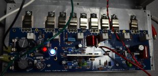
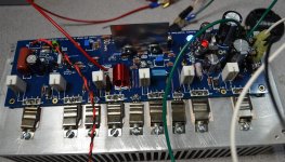
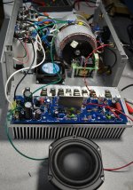
Well it’s finally done and here are the pics. I wasn't particularly picky about which brand of components I used and stuck to the prescribed values in the build guide. The only exception is the power supplies where I splashed out a bit on making sure that there was no shortage in that department, using a dedicated toroidal and smoothing capacitor bank for each channel. Basically 2 monoblocks in a single chassis. The outcome is surprisingly good – someone on this thread previously used the term “authority” to describe the amps performance and that’s probably the best way to describe it – it exerts tremendous authority over my speakers. The sound is quite forward with great low end performance and soundstage. If I compare it to my Arcam FMJ (which was a bit underpowered for my speakers) I’d say it sounds the same (i.e. very neutral) but X 2 for the authority and “size” of the sound. A very pleasing outcome and I’m dead happy!
Anyone contemplating the build I suggest go for it - it’s a whole lot of fun but take your time, do it carefully, don’t skimp on the Power Supply side and enjoy!
Attachments


You may find the PCB here, and yes, (2) boards for $39.
The diyAB "Honey Badger" Class AB Power Amp - 150W/Channel (2 Channels) - Other Amps - Power Amplifiers - PCBs
The diyAB "Honey Badger" Class AB Power Amp - 150W/Channel (2 Channels) - Other Amps - Power Amplifiers - PCBs
Looks good! Got two toroidals today and the caps so will start building and hopefully end up something like yours.
It's made by Par-Metal, but it's not on their web site. They used to sell them only on e-bay for $165.00 (not including shipping) but I don't see them on e-bay any more. You could probably get it from Par-Metal as a custom order, but I'm sure you'll pay more than $165.00.
I purchased a chassis from the diyAudio store for another build. It's very nice - heavier, more precisely machined, and more handsome than the Par-Metal. I would consider this one 4U Amplifier Chassis w/ Aluminum Heatsinks and Faceplate - Full width with 40mm Heatsinks - Chassis
I purchased a chassis from the diyAudio store for another build. It's very nice - heavier, more precisely machined, and more handsome than the Par-Metal. I would consider this one 4U Amplifier Chassis w/ Aluminum Heatsinks and Faceplate - Full width with 40mm Heatsinks - Chassis
Injured Honey Badger
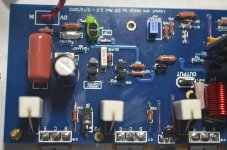
One channel of my Honey Badger stopped working after about a week of use and I'm kind of stumped.
One channel of my Honey Badger stopped working after about a week of use and I'm kind of stumped.
- All was working well for about a week of a few hours a day at moderate listening levels. Speakers are ~6R. Rails are +/- 58V.
- One day I turned it on, and the positive rail fuse one one channel blew.
- I replaced it, turned it on. It worked for ~ 5 min, then both fuses blew.
- I decided to try re-setting the 3 variable resistors. I set R17 to midway, R7 to 85R, and R30 to max resistance. I replaced the fuses with 10R resistors.
- When turned on, voltage across both resistors is 44VDC and they heat up quickly. Both the red and blue LEDs flash briefly at turn-on, then go dark.
- I found the resistance between the collector of the power resistors and the heatsink (ground) was 400R to 500R. I then found a hole in the insulator for one of the PNP power resistors (P19). OK, so this is probably what caused the problem.
- I took the board off the heatsink - same problem.
- I carefully checked all the components and solder joints. I can't find anything that looks damaged, or any bad solder joints.
- I removed P19 - same problem.
- I guessed D4 and D5 might be bad, causing a short between positive and negative rails, so I snipped them - same problem.
Attachments
Focusing on Q14 and Q15
I took a break and did some more thinking and testing. I found that ground didn't have to be grounded for the excess current problem to occur, so the positive and negative rails must either both be shorted to ground, or shorted to each other. I see from the circuit diagram that if both Q14 and Q15 had internal shorts from collector to emitter, that would account for my apparent short between the positive and negative rails. So, using the diode testing function on my multimeter, I found that resistance is 0.003R in both directions between collector and emitter of Q14. Q15 is 0.5R from collector to emitter, and 1R from emitter to collector. I found the Ebers-Moll models for bipolar junction transistors on wikipedia, and it looks like this is not supposed to happen. So unless someone tells me otherwise, I'm going to order a few MJE15032 and MJE15033 and replace those.
I took a break and did some more thinking and testing. I found that ground didn't have to be grounded for the excess current problem to occur, so the positive and negative rails must either both be shorted to ground, or shorted to each other. I see from the circuit diagram that if both Q14 and Q15 had internal shorts from collector to emitter, that would account for my apparent short between the positive and negative rails. So, using the diode testing function on my multimeter, I found that resistance is 0.003R in both directions between collector and emitter of Q14. Q15 is 0.5R from collector to emitter, and 1R from emitter to collector. I found the Ebers-Moll models for bipolar junction transistors on wikipedia, and it looks like this is not supposed to happen.
So unless someone tells me otherwise, I'm going to order a few MJE15032 and MJE15033 and replace those.I took a break and did some more thinking and testing. I found that ground didn't have to be grounded for the excess current problem to occur, so the positive and negative rails must either both be shorted to ground, or shorted to each other. I see from the circuit diagram that if both Q14 and Q15 had internal shorts from collector to emitter, that would account for my apparent short between the positive and negative rails. So, using the diode testing function on my multimeter, I found that resistance is 0.003R in both directions between collector and emitter of Q14. Q15 is 0.5R from collector to emitter, and 1R from emitter to collector. I found the Ebers-Moll models for bipolar junction transistors on wikipedia, and it looks like this is not supposed to happen.
Looks like your power stage is out. Check drivers too, make sure there is no oscillations and check for other possible shorts.
Its been three weeks now since i started using a pair of honey badgers for my front chans. Today i finished a new kit of speakers, more heavy duty and less sensitive ones that requires much more from the amplifier. But when i turn up the music to serious levels of audio, one of the channels starts to make some clipping sounds, sound almost like digital clipping.. Anyone got an idea of what could be wrong? Its not completely as the stock badger, it have 4 pairs of output transistors, was thinking that maybe EF2 might not handle it as good..? Both channels are built identically. Both channels sounds great, i mean really great. The sound got a lot more detailed, top end opened up much more, bottom end has lots of power with just no end of it and mids are top notch.
Was the speaker, not the amp.. 🙂Its been three weeks now since i started using a pair of honey badgers for my front chans. Today i finished a new kit of speakers, more heavy duty and less sensitive ones that requires much more from the amplifier. But when i turn up the music to serious levels of audio, one of the channels starts to make some clipping sounds, sound almost like digital clipping.. Anyone got an idea of what could be wrong? Its not completely as the stock badger, it have 4 pairs of output transistors, was thinking that maybe EF2 might not handle it as good..? Both channels are built identically. Both channels sounds great, i mean really great. The sound got a lot more detailed, top end opened up much more, bottom end has lots of power with just no end of it and mids are top notch.
Hi Guys,
I knew I shouldn't have clicked on this thread. Now I want to build one. I read through most of the thread and skimmed through some of it. Here's my question. I have a pair of Antek AN-5225 transformers. 25-0-25 500VA. Would these be suitable for the this amp?
Thanks, Terry
I knew I shouldn't have clicked on this thread. Now I want to build one. I read through most of the thread and skimmed through some of it. Here's my question. I have a pair of Antek AN-5225 transformers. 25-0-25 500VA. Would these be suitable for the this amp?
Thanks, Terry
There has been much discussion of transformers on this thread. See, specifically, posts #33 and #55. Generally, advice-givers have suggested higher-voltage secondaries. Of course 25+25 will work. It should work well into low impedance speakers. The only drawback is that you will not be taking full advantage of the power the HB is capable of, but that's no so bad. You can always add a higher voltage transformer later if you want.
Hi Guys,
I knew I shouldn't have clicked on this thread. Now I want to build one. I read through most of the thread and skimmed through some of it. Here's my question. I have a pair of Antek AN-5225 transformers. 25-0-25 500VA. Would these be suitable for the this amp?
Thanks, Terry
I think you could combine them to create a single 50-0-50 1000VA. That would give about +/-70Vdc rails, which is a bit high for the DiyAB but it would work.
There has been much discussion of transformers on this thread. See, specifically, posts #33 and #55. Generally, advice-givers have suggested higher-voltage secondaries. Of course 25+25 will work. It should work well into low impedance speakers. The only drawback is that you will not be taking full advantage of the power the HB is capable of, but that's no so bad. You can always add a higher voltage transformer later if you want.
When I first got into DIY I thought I had to have tons of power to get headroom. I have to be honest. Most of the time I barely have the volume cracked most of the time. Even when I do feel like listening to loud music, my Symasym can easily drive me out of the room. Even my Aleph-X can provide more than enough clean sound to satisfy and it only has 17V rails. That is why I am asking. I'm wondering if anyone has built one with this size tranny. I just tested it and it puts out +/-39VDC.
- Home
- Amplifiers
- Solid State
- diyAB Amp The "Honey Badger" build thread