Why would you choose 30-40V instead?
I have been running 800va with 45V secondaries (63V rails) since 2015 in my HB and It's still going strong.
I have tested it into a 4r dummy load close to clipping. The only thing that failed was the dummy load (4R 50W submerged in water) when I ran square waves through it.
I would choose 45V secondaries again if I should build another HB.
yngvejos, I remember your build. I believe you also went with the 21st century protection (That is my plan as well)? Nice build 🙂 .
45V will work well with my current speaker project(easy to drive 6r load). My hesitation is for lower impedences, or difficult to drive loads(phases far apart). I have speaker fever, and would like to keep all the options open in the future. 🙂
Also, I misspoke. Not that it would matter, but I have an 850VA xfmr.
The supplies and chassis are the bulk of the amplifier cost. Spend the bucks there and on good protection to allow for upgrades later. If you want to step up to lower impedance speakers in the future, you can swap out the badger boards for something more robust like a Slewmaster. The cost of the amplifier boards themselves are minimal compared to the rest of the amp.
The supplies and chassis are the bulk of the amplifier cost. Spend the bucks there and on good protection to allow for upgrades later. If you want to step up to lower impedance speakers in the future, you can swap out the badger boards for something more robust like a Slewmaster. The cost of the amplifier boards themselves are minimal compared to the rest of the amp.
I Agree. This is good advice 🙂 . Once I have a system up and running, I plan do do a lot experimenting with a second system down in my shop.
I've been reading a lot of books, and websites on electrical engineering etc. All with high hopes that I will be in a position to make some DIY audio contributions in 3-5 years from now. I find very few things in life as exciting as audio!
Dual mono PSU wiring
I'm nearly done with building the PSU after waiting for caps for the ground loop breakers (done as described by Rod Elliot's earthing ). I'm following the wiring in the picture that mbrennwa posten in POST #2905, I think i got it decently wired and I have built a mains bulb tester that i will use with a 30W halogen bulb(best i had at hands atm, will buy some bigger ones for later).
But I have some questions about how to wire the transformer and speaker protection GND's:
1: My transformers from toroidy comes with a yellow/green wire and my two separate speaker protection boards (Velleman k4700) has GND connections.
Should I wire all of these to the respective channels PSU GND and then connect the PSU GND to the respective channels ground loop breaker( which then connects to the main earthing point from the IEC inlet)? Or should these go directly to the ground loop breaker?
2: When the PSU wiring is done, could it be any harm to test it to measure correct voltages(at the last PSU cap) without having any load to it?
I hope my questions are describing enough, if not, please let me know.
I cant wait to get this amp running 😀
The yellow green wires (the shield winding connections) need to be tied to PE at the IEC inlet.
Best regards!
Best regards!
The yellow green wires (the shield winding connections) need to be tied to PE at the IEC inlet.
Best regards!
Okey, thanks for answering! By that you mean without going to the ground loop breaker first?
My transformers from toroidy comes with a yellow/green wire and my two separate speaker protection boards (Velleman k4700) has GND connections.
Should I wire all of these to the respective channels PSU GND and then connect the PSU GND to the respective channels ground loop breaker( which then connects to the main earthing point from the IEC inlet)? Or should these go directly to the ground loop breaker?..................
The green/yellow electrostatic screen wire goes directly to chassis close to where it exits from the transformer insulation.The yellow green wires (the shield winding connections) need to be tied to PE at the IEC inlet.
Best regards!
This wire carries mains interference and must not be connected to any audio carrying wires/nodes.
The green/yellow electrostatic screen wire goes directly to chassis close to where it exits from the transformer insulation.
This wire carries mains interference and must not be connected to any audio carrying wires/nodes.
Oh okey, I did not know it carried interference. Thanks for your input.
Besides it's function as an electrostatic shield, the PE winding is an element of security: It prevents an accidental connection between the primary and the lowest secondary windings. Thus it has to be connected to the IEC's PE lug as shot as possible.
Best regards!
Best regards!
No, it does not.Besides it's function as an electrostatic shield, the PE winding is an element of security: It prevents an accidental connection between the primary and the lowest secondary windings. Thus it has to be connected to the IEC's PE lug as shot as possible.
Best regards!
The impedance between the screen > chassis > PE is very low.
Using a wire link instead of using the chassis is very likely to INCREASE the impedance of that connection.
Wrong voltage after bridge rectifier with snubber
So yesterday i started testing the PSU and it didn't go so well.
Initially I wired everything up as a complete PSU and tested it with a 30W halogen bulb in series (and later a 77W with same result).
The LEDs on the slow start turned on but before the second relay could kick in, which should be after 1-1.5s it seems like the slow starter cut the power, not sure what happend.
So I then disconnected the capacitors and now it went through the "power on sequence".
I measured the voltage after the bridge rectifiers, ~40VDC, which is far to low when my transformers secondaries are rated 45VAC.
I expected ~60VDC (45*1.414 minus voltage drop from diods) after rectification.
At first I thought it was a faulty slow start module but it was the same behavior on both sides(dual mono setup).
I measured the output voltage from the slow starts, 225VAC, which I think is acceptable. Then i disconnected the ac input from one of the bridge rectifiers and measured 45.7VAC, which is perfect.
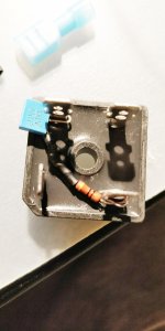
On my bridge rectifiers I have soldered on a snubbers. Could these be what causing the low voltage? The snubber is a 10Ohm 1W resistor with a 100nF 100V capacitor LINK TO CAPACITOR ON MOUSER
These are connected on the AC-side of the bridge rectifier as shown on the attached picture.
I hope you guys have some time to read and give me some help with this, please let me know if more info or pictures are needed 🙂
So yesterday i started testing the PSU and it didn't go so well.
Initially I wired everything up as a complete PSU and tested it with a 30W halogen bulb in series (and later a 77W with same result).
The LEDs on the slow start turned on but before the second relay could kick in, which should be after 1-1.5s it seems like the slow starter cut the power, not sure what happend.
So I then disconnected the capacitors and now it went through the "power on sequence".
I measured the voltage after the bridge rectifiers, ~40VDC, which is far to low when my transformers secondaries are rated 45VAC.
I expected ~60VDC (45*1.414 minus voltage drop from diods) after rectification.
At first I thought it was a faulty slow start module but it was the same behavior on both sides(dual mono setup).
I measured the output voltage from the slow starts, 225VAC, which I think is acceptable. Then i disconnected the ac input from one of the bridge rectifiers and measured 45.7VAC, which is perfect.
On my bridge rectifiers I have soldered on a snubbers. Could these be what causing the low voltage? The snubber is a 10Ohm 1W resistor with a 100nF 100V capacitor LINK TO CAPACITOR ON MOUSER
These are connected on the AC-side of the bridge rectifier as shown on the attached picture.
I hope you guys have some time to read and give me some help with this, please let me know if more info or pictures are needed 🙂
Attachments
Can you post a schematic of how you've got everything connected? A couple good pictures of your supply connections would help too. It sounds like you have something connected wrong, but we're guessing without having any info to go on.
Can you post a schematic of how you've got everything connected? A couple good pictures of your supply connections would help too. It sounds like you have something connected wrong, but we're guessing without having any info to go on.
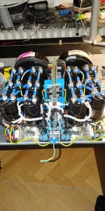
Yes, the build is kind of a tight fit so not every cable is visible.
First attached is picture of the PSU wiring I'm trying to follow that mbrennwa posten in POST POST #2905 with the difference that mine is with 45VAC secondaries.
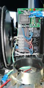
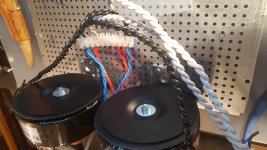
The second picture is shows some of the wiring. The pictures where taken before testing and before i started i removed the green/yellow PE wire that comes from tranformer and connected it to chassi instead. I also lifted the green/yellow PE wire from the speaker protection while trying to find the fault. Here you also can see the black wire from PSU-0V going to the ground loop breaker.
Ground loop breaker is a 35A bridge rectifier with 10Ohm 5W resistor in parallel with 100nF x2 capacitor.
On the third picture i have removed to capacitors to be able to show the connection to the slow start. The brown and blue cable on the bottom is the L+N in to the slow start. The brown and blue above is L+N out to transformer(white wires) and speaker protection boards that sits above.
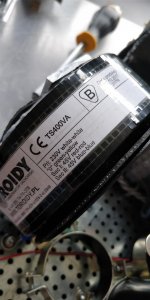
Fourth picture is the transformer info.
Fifth picture shows how the secondaries is wired before caps and slow start was installed as you cant really see it in the other pictures. Basically the wires where to short to reach the other side of the chassi so I made the connection joint(wich now sits under/between the transformers) and the run the sec-wires to the bridge rectifiers.
I know this probably looks like a mess but it's my first build 🙂
Am i incorrect thinking that i should get ~60VDC from my 45VAC secondaries after rectification?
Best regards
Ejje
Attachments
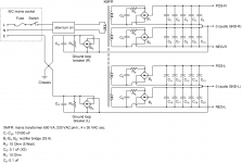
I normally expect to see 63 - 64VDC with no load from a 45VAC output transformer. Voltage may be higher with poor self regulation of the transformer. Your schematic looks correct. Your next step should be to test everything in stages. Power up one transformer with bridges only connected and see what output is. Next add cap banks and check voltages again ( this should be considerably higher than transformers alone). Next connect the ground potentials between cap banks and measure again (voltage shouldn't change). Next add your loop breaker and measure again. Repeat for the second channel.
So I then disconnected the capacitors and now it went through the "power on sequence".
I measured the voltage after the bridge rectifiers, ~40VDC, which is far to low when my transformers secondaries are rated 45VAC.
I expected ~60VDC (45*1.414 minus voltage drop from diods) after rectification.
You have tro expect this voltage only when a filter capacitor is connected to the rectifier's DC terminals.
Btw, your pictures show that you have connected the electrolytics to the rectifiers by a pair of twisted wires of the same colour. In order to avoid confusion, don't do that! I suspect that your electrolytics are polarized the wrong way.
Best regards!
I normally expect to see 63 - 64VDC with no load from a 45VAC output transformer. Voltage may be higher with poor self regulation of the transformer. Your schematic looks correct. Your next step should be to test everything in stages. Power up one transformer with bridges only connected and see what output is. Next add cap banks and check voltages again ( this should be considerably higher than transformers alone). Next connect the ground potentials between cap banks and measure again (voltage shouldn't change). Next add your loop breaker and measure again. Repeat for the second channel.
I will be sure to try this as described as soon as i get home again! 🙂
You have tro expect this voltage only when a filter capacitor is connected to the rectifier's DC terminals.
Btw, your pictures show that you have connected the electrolytics to the rectifiers by a pair of twisted wires of the same colour. In order to avoid confusion, don't do that! I suspect that your electrolytics are polarized the wrong way.
Best regards!
Okey, but is it normal to measure 40VDC on rectifiers DC terminals without capacitors connected when i have measured 45.7VAC coming in on the AC terminals from the transformers secondaries? ( as described in post #2932 )
Yes sorry, I understand that it is confusing to use same color wire for + and -. I did check the wires with a DMM before connecting and marked out the minus connection with some black electrical tape(hardly visible on the pictures tough). I will try to get some in another color.
post #2932[/URL] )
Output voltage will be considerably lower with no capacitors connected and will vary a lot between different volt meters as well. This voltage contains huge amounts of ripple without capacitors so it is difficult to measure without something to stabilize it.
post #2932[/URL] )
Output voltage will be considerably lower with no capacitors connected and will vary a lot between different volt meters as well. This voltage contains huge amounts of ripple without capacitors so it is difficult to measure without something to stabilize it.
Aha, now i understand! My cheap DMM provided from my school is probably not the best.. hehe. I will report back when I have tested more later! 🙂 Thanks
Hi Ejje,
When you are learning especially, it is important that your testing equipment doesn't "lie" to you. The cheap meters are often very, very inaccurate (ignore the fact that it has digits instead of a meter movement). It would help you to think, "it's about 40 VDC" instead of something like "it's 40.3 VDC". Often the last digit isn't even close to reality and they won't even meet the specifications printed on the box or the manual.
For an idea, very good meters are 0.03% accurate, 0.05% being common. The inexpensive meters are usually spec'd at 0.5% accurate and they are often out of tolerance even new out of the box. Other specs, like AC volts and ohms will be worse than the DC accuracy even with very good meters. The last point I have to make is that cheap meters are easily damaged where good ones can usually tolerate big mistakes. That means that as you learn, you may go through a bunch of cheap meters (and never get the right answer!).
Lastly, the mV scale is critical since that is your bias current and DC offset adjustments or checks. The inexpensive meters are often so wildly inaccurate that you might be further ahead feeling the temperature of the heat sinks, or looking at mains AC current draw with an analogue meter. I'm not suggesting that you do it this way, just trying to illustrate how useless a cheap meter can be. If you own one good meter, you can test the cheap ones and know what they errors are (transfer of calibration toa cheap meter), but when you consider AC voltages, use the good meter.
-Chris
When you buy a meter for yourself, make the first one at least semi-good. Make certain that it has "true rms" for AC voltages. While you are looking, try to get one where the AC frequency response is a lot higher than 1 KHz. You may find that 100 KHz won't be that much more money.My cheap DMM provided from my school is probably not the best..
When you are learning especially, it is important that your testing equipment doesn't "lie" to you. The cheap meters are often very, very inaccurate (ignore the fact that it has digits instead of a meter movement). It would help you to think, "it's about 40 VDC" instead of something like "it's 40.3 VDC". Often the last digit isn't even close to reality and they won't even meet the specifications printed on the box or the manual.
For an idea, very good meters are 0.03% accurate, 0.05% being common. The inexpensive meters are usually spec'd at 0.5% accurate and they are often out of tolerance even new out of the box. Other specs, like AC volts and ohms will be worse than the DC accuracy even with very good meters. The last point I have to make is that cheap meters are easily damaged where good ones can usually tolerate big mistakes. That means that as you learn, you may go through a bunch of cheap meters (and never get the right answer!).
Lastly, the mV scale is critical since that is your bias current and DC offset adjustments or checks. The inexpensive meters are often so wildly inaccurate that you might be further ahead feeling the temperature of the heat sinks, or looking at mains AC current draw with an analogue meter. I'm not suggesting that you do it this way, just trying to illustrate how useless a cheap meter can be. If you own one good meter, you can test the cheap ones and know what they errors are (transfer of calibration toa cheap meter), but when you consider AC voltages, use the good meter.
-Chris
- Home
- Amplifiers
- Solid State
- diyAB Amp The "Honey Badger" build thread