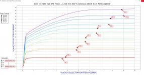
Definitely, genuine and they were plotted on my cure tracer as a double check. Many of the other parameters were verified by @jjs in the lab.I have Sanyo datasheets for those devices, do not believe Toshiba made them, also notice the exposed pad where as the ksa,ksc versions have a thicker bodies and are isolated
Attachments

just bumping this in case it was missed. ThanksIs a 50v Rated cap ok for C9?
just bumping this in case it was
Make it 63v 😉just bumping this in case it was missed. Thanks
JT
Hint: You always want a margin for sideways, a 50v cap doesn't have that. 😉
Last edited:

I checked the hFE on my KSC3503DS/KSA1381ESTU combos and the KSC3503DS are 84 and the KSC3503DS run from 109-112. Anyone want to PM me about KSC3503E availability? Also, I installed the combo I have in the CCS1 on the input board. Would it be advisable to replace those also or no problem.
Yes for sure. I just wasn't sure the voltages at that location. Thanks for verifying! I have 63v but only 50v available to match my other caps is why I was wondering. ThanksJT
Hint: You always want a margin for sideways, a 50v cap doesn't have that. 😉
C9 connects a virtual zero volt node to earth in the feedback return of a differential amp. In operation it is there to block minor DC input or feedback bias voltages. Large DC voltages across C9 could only result from catastrophic failures in the output section and be momentary. The AC voltage across C9 will be the same as the amplifier input voltage. Thus 50v rated will be fine for normal operation.Yes for sure. I just wasn't sure the voltages at that location. Thanks for verifying! I have 63v but only 50v available to match my other caps is why I was wondering. Thanks
Awesome thanks for the very detailed response.! Now my caps can match lol.C9 connects a virtual zero volt node to earth in the feedback return of a differential amp. In operation it is there to block minor DC input or feedback bias voltages. Large DC voltages across C9 could only result from catastrophic failures in the output section and be momentary. The AC voltage across C9 will be the same as the amplifier input voltage. Thus 50v rated will be fine for normal operation.
One last question in regards to the caps. Is there any harm in substituting the 10uf caps with 22uf?
Assume you refer to C3. Power up for the larger capacitor potentially changes the timing of the stabilisation of the current sources CCS1 and CCS2. I would be cautious and not do it. All of our testing (stress and parametric) was done with 10u.Awesome thanks for the very detailed response.! Now my caps can match lol.
One last question in regards to the caps. Is there any harm in substituting the 10uf caps with 22uf?
Thanks Jeremy,Yes, disparity in the driver is concerning. I ran your scenario with the driver NPN hfe=130 and PNP hfe=210 in sim. I saw 20kHz .000103% THD with the drivers matched and 20kHz .000109% THD for your situation. Needless to say but the distortion was hardly affected. The current mirror and the TMC feedback really throw the distortion into the mud. The current mirror is the most important to match along with it's emitter resistors.
The 2sc5171/2sa1930 trade SOA for speed, because of this I don't recommend them as drivers for 4ohm use greater than 50V rails.
Jeremy
Hi Jeremy
My plan is
Outputs: 2SC5359/2SA1987
Drivers: MJE15034G/MJE15034G
Pre-Drivers: KSC3503ESTU/KSA1381ESTU
+/- 71V rails
Heatsinks: 300 x 160 x 40 mm
My speakers are 300W/4Ω
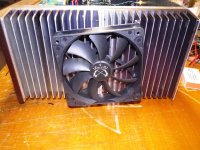
what do you believe ? its small ? i can put external fan controlled ....very very quiet..
Also a have this question, for +/- 71V rails , must go for EF4 output board this is binding?? or can i go with EF3 output board and +/- 71V rails??
My plan is
Outputs: 2SC5359/2SA1987
Drivers: MJE15034G/MJE15034G
Pre-Drivers: KSC3503ESTU/KSA1381ESTU
+/- 71V rails
Heatsinks: 300 x 160 x 40 mm
My speakers are 300W/4Ω
what do you believe ? its small ? i can put external fan controlled ....very very quiet..
Also a have this question, for +/- 71V rails , must go for EF4 output board this is binding?? or can i go with EF3 output board and +/- 71V rails??
Sorry Guys I cut a pasted the rail data for the 300mm to the 400mm deep heatsinks. Here are the corrected values.
3U 0.40°C/W, 40×120×300mm ~50V rails
4U 0.31°C/W, 40x165x300mm ~60V rails
5U 0.18°C/W, 40x210x300mm ~70V rails
3U 0.25°C/W, 40x120x400mm ~60V rails
4U 0.19°C/W, 40x165x400mm ~70V rails
5U 0.14°C/W, 40x210x400mm ~80V rails
Jeremy
Attachments
Last edited:
Hi Guys,
I am looking for KSC3503E to match with my KSA1381ESTU
If someone can provide me with a few of them, please send me PM.
Many thanks
Theo
I am looking for KSC3503E to match with my KSA1381ESTU
If someone can provide me with a few of them, please send me PM.
Many thanks
Theo
😉😉😉😉Hi Guys,
I am looking for KSC3503E to match with my KSA1381ESTU
If someone can provide me with a few of them, please send me PM.
Many thanks
Theo
Again, if anyone has any KSC3503E that they are willing to part with please send me a PM.
Thanks
Thanks
Hi Jeremy
My plan is
Outputs: 2SC5359/2SA1987
Drivers: MJE15034G/MJE15034G
Pre-Drivers: KSC3503ESTU/KSA1381ESTU
+/- 71V rails
Heatsinks: 300 x 160 x 40 mm
My speakers are 300W/4Ω
what do you believe ? its small ? i can put external fan controlled ....very very quiet..
Also a have this question, for +/- 71V rails , must go for EF4 output board this is binding?? or can i go with EF3 output board and +/- 71V rails??
You probably won't need that fan for normal use. If your bench testing into 4 ohms you might need it versus playing music. I guess what I'm saying if you know your going to be running it hard you can blow an external fan on the sinks to keep it cool. If you have to blow a fan on it all the time then your heatsinks are probably too small but I doubt that from the size of your heatsinks.
If you want to run 70V rails at 4 ohms your best bet it use the 4 pair board because you'll have more transistors to choose from. To run 70V on 3 pair you need at the very least a 200W transistors like MJL4281/MJL4302, 2SC2922/2SA1216, 2SC3264/2SA1295, and MG6331/9411.
Jeremy
Last edited:
Please add your location to these requests.Again, if anyone has any KSC3503E that they are willing to part with please send me a PM.
Thanks
Again, if anyone has any KSC3503E that they are willing to part with please send me a PM.
Thanks
I'm in the UK, Thanks
People looking for the 2sc3503estu!!!!
https://www.diyaudio.com/community/threads/some-components-for-sale.314633/
I actually have all the transistors needed for this project.
https://www.diyaudio.com/community/threads/some-components-for-sale.314633/
I actually have all the transistors needed for this project.
"Normal operation?" You don't design for, "normal operation." you design for the sh8t you haven't thought of, or can't happen, but does.C9 connects a virtual zero volt node to earth in the feedback return of a differential amp. In operation it is there to block minor DC input or feedback bias voltages. Large DC voltages across C9 could only result from catastrophic failures in the output section and be momentary. The AC voltage across C9 will be the same as the amplifier input voltage. Thus 50v rated will be fine for normal operation.
Last edited:
Now I don't know lol. Both you guys were part of the team. Is the voltage 0 at c9 or Rail voltage?"Normal operation?" You plan for the abby normal and hope for the best. That cap will not support rail voltage, so for 50ty cent, I'll use the schematic that allows for abby problems.
- Home
- Amplifiers
- Solid State
- DIYA store "Wolverine" (Son of Badger) .... suggestions ??