Not yet... Harry and I are currently reviewing the BOM and silkscreenhi, sorry, there are finished pcb, bom or guide x realize ?? thank you🙂
We have found a few issues so it's certainly been worth the time spent
Update
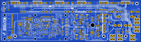
Hi OS, Harry and I have been giving the BOM and Silkscreen sizes a close going over.
We had to tweak a few Caps but we are nearly there.
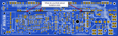
I was wondering what you think about adding Isolation slots as shown in the Image or in any other location.
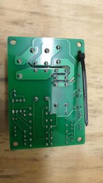
I used them on my Soft Start PCB (attached)
Hi OS, Harry and I have been giving the BOM and Silkscreen sizes a close going over.
We had to tweak a few Caps but we are nearly there.
I was wondering what you think about adding Isolation slots as shown in the Image or in any other location.
I used them on my Soft Start PCB (attached)
Attachments

Updated as Shown.
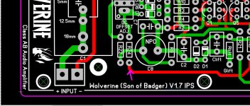
I managed to rotate R105 and move C109 down.
It looks a lot better now. 😀
Harry is just checking the BOM.
You can't change Q103's position. It must line up with Q108 for
thermal FB.
Q103 bolts to Q108 , all 3 (Q108,107,103) have a small aluminum plate common.
OS
Last edited:
R24 approved !! Good deal.oh nice got the file I have to delete the last post lol can we change R24 like this?
Just move the V- rail (further) away from the mounting screw.
OS
Hi OS,You can't change Q103's position. It must line up with Q108 for
thermal FB.
Q103 bolts to Q108 , all 3 (Q108,107,103) have a small aluminum plate common.
OS
Yes I thought you might be sharing the mounting bolt. But Q108 is going to sit alot higher on the heatsink plate.
If Q103's mounting hole is to line up with Q108's mounting hole it will be sticky out the board along way.
So there is a few options what would you like me to do.
1. Move Q103 back up so the centers align.
2. Move Q108 down so the centrs align.
3 move Q103 up a bit and move Q108 down a bit so the centres align.
4. There is on other option. If we use a 3mm aluminium heatsink plate we can just leave it as is and just drill and tap two holes and use a short screw for Q103 as it can now sit lower down closer to the board. The screw from Q108 can go through and won't hit Q108. The centers are only offset 2.8mm anyway.
If I moved it down this is what it would look like.
What do you think?

Ok I'll make those changes.R24 approved !! Good deal.
Just move the V- rail (further) away from the mounting screw.
OS
What did you think about post #644?
Hi OS,
Yes I thought you might be sharing the mounting bolt. But Q108 is going to sit alot higher on the heatsink plate.
If Q103's mounting hole is to line up with Q108's mounting hole it will be sticky out the board along way.
So there is a few options what would you like me to do.
1. Move Q103 back up so the centers align.
2. Move Q108 down so the centrs align.
3 move Q103 up a bit and move Q108 down a bit so the centres align.
4. There is on other option. If we use a 3mm aluminium heatsink plate we can just leave it as is and just drill and tap two holes and use a short screw for Q103 as it can now sit lower down closer to the board. The screw from Q108 can go through and won't hit Q108. The centers are only offset 2.8mm anyway.
If I moved it down this is what it would look like.
What do you think?View attachment 946154
I had someone early in the thread mount a TO-126/TO-3P "sandwich".
Original HK EF3 screwed all 3 devices together (heatshrink tubing ,actually)
Another TO - xx "sandwich".
Both case styles mate nicely at the same height with sufficient lead space/length.
Moving them as long as they align is alright.
Those arc gaps along the output rail are for continuous 120VAC . We
usually run 5-50V (normal listening). Standard creepage will do.
OS
Done, I moved them a bit each way. 🙂
I will check in with Harry today but I believe we are done.
Once I hear from him and make any necessary changes I will submit to you the final version for your final review.
I also updated the pads on C109
Attachments
Last edited:
With all the updates , was the UMS mounting spec. re-confirmed.
This project has 1 extra (pre-existing) hole near the power connections and uses a
pre-existing UMS hole for the Vbe.
OS
This project has 1 extra (pre-existing) hole near the power connections and uses a
pre-existing UMS hole for the Vbe.
OS
This one looks different.
Solid state amp projects -
Most are the same, V+/- at opposite ends of the PCB. Blocky ground returns.
Vbe snakes through the OP/Rail area.
They all work , are popular.
250k - 600K bandwidth amps aren't picky.
The Wolverine or badger aren't too picky , either. My sub amp (blameless).
is overcompensated with a big block layout. NO star.
Spook and Hellraiser are 2.2mhz and over 3Mhz.
OS
If you send me the dimensions I'll double check.With all the updates , was the UMS mounting spec. re-confirmed.
This project has 1 extra (pre-existing) hole near the power connections and uses a
pre-existing UMS hole for the Vbe.
OS
Hi OS,
I can confirm that the Holes line up.
Yes, there is 1 extra hole near the GND of the V+ and V- connections.
It also appears from the PDF you provided that the VBE hole is an extra.
Measuring -20mm, 20mm relative to the hole at the base of Q108.
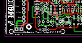
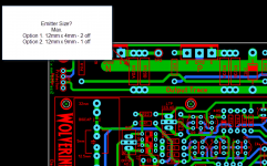
Harry & I have been checking over the BOM and PCB to ensure all the parts will fit. This afternoon Harry was checking over the Emitter resistors and wasn't finding a lot of resistors that would fit in the space provided. He searched Digikey and Mouser.
Below is a Image of what we have so far.
Can you please advise what was your plan for emitter resistors.
I guess another option would be to stretch the top of the PCB but keep the mounting holes in the same position.
Currently the bottom of the PCB is overlapping 10mm from the bottom holes and 6mm from the top holes. I think that an extra 4mm would help.
But we seek your guidance on how to proceed.
I have included a snippet from his BOM to make comparison easier.
I can confirm that the Holes line up.
Yes, there is 1 extra hole near the GND of the V+ and V- connections.
It also appears from the PDF you provided that the VBE hole is an extra.
Measuring -20mm, 20mm relative to the hole at the base of Q108.
Harry & I have been checking over the BOM and PCB to ensure all the parts will fit. This afternoon Harry was checking over the Emitter resistors and wasn't finding a lot of resistors that would fit in the space provided. He searched Digikey and Mouser.
Below is a Image of what we have so far.
Can you please advise what was your plan for emitter resistors.
I guess another option would be to stretch the top of the PCB but keep the mounting holes in the same position.
Currently the bottom of the PCB is overlapping 10mm from the bottom holes and 6mm from the top holes. I think that an extra 4mm would help.
But we seek your guidance on how to proceed.
I have included a snippet from his BOM to make comparison easier.
Attachments
That won't work at this end.Slant/angle the resistors from straight up and down?

- Home
- Amplifiers
- Solid State
- DIYA store "Wolverine" (Son of Badger) .... suggestions ??