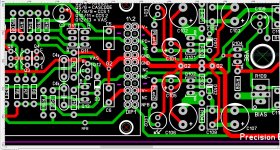
The creepage thing is why I opted to lay out the NS inputs that way they are. PD+, NFB and ND- are all in one plug with only a few volts difference between pins. I put the power connector between the input and VAS. The power connector pins are maximum 60VDC difference between pins with our external regulators. Worked out very well!
BOM ... finally.
A stupid (me) hard shutdown of my Xeon to put in gold/silver SATA HDD cables wiped
half my BOM out a few days ago.
Now it's finished.
Last two entries are interesting.
I never looked up the most expensive of the output device choices.
WOW !!! The ON semi MJL4281A/4302A pair are "beasts".
350Vceo devices @ 4A DC and 6+A 100m/sec SOA.
Similar to Sanken 230W MT-200's.
These devices could match the 5mm rail trace Imax.
Even as these devices are 7USD each , Mouser will have 1000 of each
tomorrow.
12/15A fuses for the rails and you have a 400W Wolverine.
On my 3 pair Sanken unit , I could light up toaster Nichome wire and
drive a paralleled 4R DVC 500W car sub to Xmax.The amp would just
get moderately warm with 55V rails.
The MJL4281A/4302A pair does have a higher Cob @ 600pF. R111
would definitely be 82R - 100R and C112 , "up it" to 1uF (suckout cap).
But in the end a "beast you would have".
I actually TRIED to blow up a Sanken slew.
Nearly impossible. Screw up , pop in a fuse ... continue.
Also calculated the 1mm/1.26mm(18/16ga) L1 winding.
The BOM is quite specific. A "beast" would require option 2.
OS
Attachments
MJL4281A/4302A are great devices but not as tough as the Sankens. They will blow up if you make a mistake where the Sankens just blow fuses.
The creepage thing is why I opted to lay out the NS inputs that way they are. PD+, NFB and ND- are all in one plug with only a few volts difference between pins. I put the power connector between the input and VAS. The power connector pins are maximum 60VDC difference between pins with our external regulators. Worked out very well!
Yes , good choice. they are also in phase (not perfect , but close).
Stuart needs to bring PD+/ND- closer to G2. Why ... at idle , PD+/ND-
sit a roughly +2V/-1.8V. At full power each can swing rail to rail -5V.
So you could have a 115V potential between PD+ and V+. A G2/PD+
potential could only be 55V. Better.
OS
Yes, the power rails are the scary voltage to have any large voltage swings near by. Plan B would be to put PD+. NFB and ND- together at one end of the connector with an empty pin separating them from the rest, but that's a big rework.
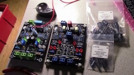
I put a set in my honey badger about 1.5 months agoI have 6 pairs of MJL4xxx set aside for this 🙂.
I thought they were discontinued?


I have 6 pairs of MJL4xxx set aside for this 🙂.
I thought they were discontinued?
No , Mouser is going to get 1K of the PNP's tomorrow.
Neither gender says obsolete. I was viewing the MJL4302/4281AG version.
Just the 4302 have a 4/21 delivery date
PS - The 4302/4281 A's are obsolete.
OS
I have 6 pairs of MJL4xxx set aside for this 🙂.
I thought they were discontinued?
On Semi has been scaring a lot of people for years by adding a G to the end of the part number to indicate lead free, then marking the previous version obsolete. I think these will be around for a while.
Nice Badger! Thank's for the info guys! I Remember the sankens being discontinued, and then I got the MJL EOL notice from mouser. I was starting to worry about outputs!
I believe Pete reduced the worry a lot with this modular design! I'll have to order extra though, I'd like to do a second system for the shop eventually.
I believe Pete reduced the worry a lot with this modular design! I'll have to order extra though, I'd like to do a second system for the shop eventually.
No , Mouser is going to get 1K of the PNP's tomorrow.
Neither gender says obsolete. I was viewing the MJL4302/4281AG version.
Just the 4302 have a 4/21 delivery date
PS - The 4302/4281 A's are obsolete.
OS
I am getting Sanken 2sa2223AY and 2sc6145AY from profusionplc hfe ~100. I think they are a good option too.
I am getting Sanken 2sa2223AY and 2sc6145AY from profusionplc hfe ~100. I think they are a good option too.
They are very nice BJTs! D'Agostino use them as output devices too.
Sajti
Hi OS,Yes , good choice. they are also in phase (not perfect , but close).
Stuart needs to bring PD+/ND- closer to G2. Why ... at idle , PD+/ND-
sit a roughly +2V/-1.8V. At full power each can swing rail to rail -5V.
So you could have a 115V potential between PD+ and V+. A G2/PD+
potential could only be 55V. Better.
OS
I was talking to Harry and he suggested maybe we can use a larger pitch plug to solve the creepage problem on the pads of the DIP
Maybe a 4.2mm pitch could work.
You may also be able to use a 6 position like this.

Just use a 12 position version of what you are using. Space the connections
out.
The reason ??? The use of common PC jumpers to bridge the connections.
2.54mm pitch is also more universally available.
OS
out.
The reason ??? The use of common PC jumpers to bridge the connections.
2.54mm pitch is also more universally available.
OS
I'm sure the Badger had borderline creepage issues. It's good that 3 layout
people are swapping designs.
Creepage with this one is more important. Slew/Wolverine is a 50-85 ! volt
design. Badger was strait 60V.
I don't remember this much fussing over the Badger layout - but we know
more and this is good !!
Some may be scared of a 85V rated amp. Yamaha did it. I repaired a 2 pair per
channel natural sound amp. It had 82V rails/10Kuf per channel PS .. and
a trafo that was slightly under-rated for 2 amps like this.
This amp could belt out a transient of 5db over rated power. I sure it could not
"hold" a 150V p-p signal , the PS would "fold" under that load.
Basically , the amp could throw out 400w peaks while rated at 135W RMS.
Wolverine has the Cap multipliers ... wildly fluctuating PS's are no issue here.
PS - that Yamaha was a "scary" amp to listen to at high levels !!!!
OS
Last edited:
sure OS the file that stuart post here #576
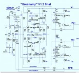
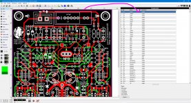
I just did the 12 pin thing I was doing the components ID I haven't finish yet, also because ST is working on it I really don't want to mess this up too 😛 since all macros are made already as components they can have ID and value and that generate a BOM exporting to text easily I did the same with the Greenamp The Green Arrow version you did last year the schematic "I don't remember" lol
yes the Greenamp PCB V1.2 I tested and sounds really good just that I don't have proper tools to give and inform accurate results 🙁
I'm gonna attached here as example 🙂
Attachments
Last edited:
- Home
- Amplifiers
- Solid State
- DIYA store "Wolverine" (Son of Badger) .... suggestions ??