Hi OS,
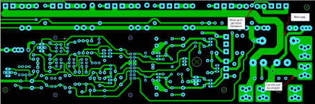
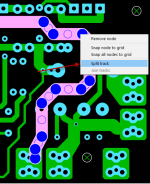
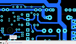
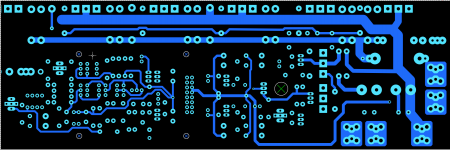
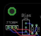
I like to isolate the top and bottom copper layers to see that layout of the traces
in isolation. This way you can spot if traces are to close of if there is a better route to the same net.
I have just marked up a few that I see straight away.
I sure you probably do this but I'm just trying to help out.
You will also need an outline and I think some silkscreen over the holes looks great. I posted a macro with the outline for you to use as a starting point if you like.
Attachments

Spice Analysis Support for newWolverine project?
Hi all!
Is tere any interest getting simulation support for your latest version of wolverine?
My simulation-project has come to a stage, which allows to extend schematics and concepts. The old wolverine is on my todo-list, but it might make more value to do it with a new on-going project.
Which simulation capabilities can I offer?
1. schematics, BOM and spice-netlist in KiCad.
2. Offset compensation
3. DC-Linearity assessment with Bias-current optimisation
4. AC-Linearity assessment @100Hz, 1kHz, 10kHz, 20kHz
5. Bode-plots (magnitude, phase, phase-delay), Power bandwidth & phase
6. Slew-rate assessment
7. THD assessment with fourier
8. IMD assessment acc. CCIF-2, CCIF-3, SMPTE RP120 and DIN45403
9. dynamic intermodulation DIM/TIM acc. IEC20268-3 (Otala/Curl) and
"simplified TIM" acc. Skritek
10. Open-loop behavior acc. Tian and Middlebrook
11. SOA analysis
12. All m.a. analysis is performed with 8Ohm, 4Ohm and linear loudspeaker model
13. PDF-report generated from LaTex
What I need is an updated schematic and BOM.
Any interests?
Last edited:
Hi OS,
I like to isolate the top and bottom copper layers to see that layout of the traces
in isolation. This way you can spot if traces are to close of if there is a better route to the same net.
I have just marked up a few that I see straight away.
I sure you probably do this but I'm just trying to help out.
You will also need an outline and I think some silkscreen over the holes looks great. I posted a macro with the outline for you to use as a starting point if you like.
Thank you , Stuart. Yes , ground /rail creep near C113 ... while not critical -
is fixed.
Circles around mounting screws ... nice !
Your best idea was the preformed TO-92's. Thanks !
OS
Hi all!
Is tere any interest getting simulation support for your latest version of wolverine?
My simulation-project has come to a stage, which allows to extend schematics and concepts. The old wolverine is on my todo-list, but it might make more value to do it with a new on-going project.
Which simulation capabilities can I offer?
1. schematics, BOM and spice-netlist in KiCad.
2. Offset compensation
3. DC-Linearity assessment with Bias-current optimisation
4. AC-Linearity assessment @100Hz, 1kHz, 10kHz, 20kHz
5. Bode-plots (magnitude, phase, phase-delay), Power bandwidth & phase
6. Slew-rate assessment
7. THD assessment with fourier
8. IMD assessment acc. CCIF-2, CCIF-3, SMPTE RP120 and DIN45403
9. dynamic intermodulation DIM/TIM acc. IEC20268-3 (Otala/Curl) and
"simplified TIM" acc. Skritek
10. Open-loop behavior acc. Tian and Middlebrook
11. SOA analysis
12. All m.a. analysis is performed with 8Ohm, 4Ohm and linear loudspeaker model
13. PDF-report generated from LaTex
What I need is an updated schematic and BOM.
Any interests?
Yes , # 1 ... A better schema and BOM. Preferably , a one click list for
both Digikey and Mouser.
And the rest , even as we kind of know how this classic design will ultimately
perform.
Thanks ,
OS
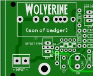
Ooooh , that is sweet.
I'd love to have a better Wolverine macro and artwork.
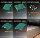
Who made the spooky , slewmonster artworks ... they are the bomb.
Cool style. We might get a "cult" following.😀
PS - it's the Hellraiser(greenamp) and the Spooky V2 that will be the two addon
boards for this store project. They will have servo's that do not touch the signal path
and be a hybrid SMD/through -hole "adventure".
They need Artwork/branding ....
OS
I'd love to have a better Wolverine macro and artwork.
Who made the spooky , slewmonster artworks ... they are the bomb.
Cool style. We might get a "cult" following.😀
PS - it's the Hellraiser(greenamp) and the Spooky V2 that will be the two addon
boards for this store project. They will have servo's that do not touch the signal path
and be a hybrid SMD/through -hole "adventure".
They need Artwork/branding ....
OS
Last edited:
Hi OS,
Well...such is life. Thanks for your time.
kr, sepp2gl
This is something, that I'd like to have either, but for the moment it is unfortunately out of scope of my current activity.Yes , # 1 ... A better schema and BOM. Preferably , a one click list for
both Digikey and Mouser.
This sounds like a (polite) "No, thanks".And the rest , even as we kind of know how this classic design will ultimately
perform.
Thanks ,
OS
Well...such is life. Thanks for your time.
kr, sepp2gl
Ooooh , that is sweet.
I'd love to have a better Wolverine macro and artwork.
Who made the spooky , slewmonster artworks ... they are the bomb.
Cool style. We might get a "cult" following.😀
They need Artwork/branding ....
OS
I did the spooky and wolverine art on the original SlewMaster boards, not sure who did the others.
If I'm recalling correctly I grabbed some line art or similar on line and used a fine trace to outline and produce filled zones on the silk layer, joining unconnected zones into a single macro. Was fiddly but worked well.
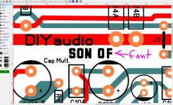
Hey , can you make me a smaller version of that.
One about as big as the "DIYaudio" logo. Also make a fancy diyaudio , as well.
Thanks.
PS - a small cute ghost (spooky) and a Wolverine (charactor) image is needed.
You will see why.
OS
One about as big as the "DIYaudio" logo. Also make a fancy diyaudio , as well.
Thanks.
PS - a small cute ghost (spooky) and a Wolverine (charactor) image is needed.
You will see why.
OS
Last edited:
The sharp corners on that font may not come through well on the silkscreen, which has a high surface tension in liquid form.
BOO !! Spooky V2 ....
What a neat (different) design (below 1). I want one for me SUB !!
I will lobby to try to have this as a store option. Wait till you see my
layout on this one !!
NO Servo !! Ha ! 😛
1. - Since the BCxxx P channel devices seem to model with less beta in general ,
Just a single trimmer (R6 - 500R) is needed to balance this beta (imbalance).
Since R18 "bleeds" off excess current to establish the VAS mA's , the general IPS current
is not as important. (better than V1.2)
So , offset is determined by the cap C5 (and R6). No "dirty servo".
Q1-4 on the layout will be REAL close , a drop of thermal paste ... heat-shrink
all 4 together.
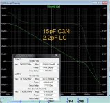
2. - C3/4 and C7. C3/4 can go as low as 10pF with 2.2 - 3.3pF lead compensation.
This amp has crazy bandwidth. Optimal with C3/4 = 15pF
and LC/C7 at 2.2pF (below 2). Margin is better than the Wolverine even
at this obscene UG.
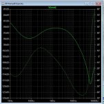
3. - What was I thinking ? Shunt regulators on the V1.2 ???
Way better (and cold) with the zener pass regs. Ghosts are COLD! 😀
(below 3) PSRR is way better here.
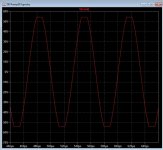
4. - CLIPPING !! NO match ... Hawksford will clip all day (below 4)-(self clamping).... LEDs (D5-8) ,
will pulse. Funny the OPS bias reduces from 75mA to 48mA with heavy
overload. This is actually good.
This is SIMPLE. Just 14 X Q / 24 -R / 7 - C / 6 -D , most are similar values/
types. AND it performs better ...can't lose here.
LT attached.
OS
What a neat (different) design (below 1). I want one for me SUB !!
I will lobby to try to have this as a store option. Wait till you see my
layout on this one !!
NO Servo !! Ha ! 😛
1. - Since the BCxxx P channel devices seem to model with less beta in general ,
Just a single trimmer (R6 - 500R) is needed to balance this beta (imbalance).
Since R18 "bleeds" off excess current to establish the VAS mA's , the general IPS current
is not as important. (better than V1.2)
So , offset is determined by the cap C5 (and R6). No "dirty servo".
Q1-4 on the layout will be REAL close , a drop of thermal paste ... heat-shrink
all 4 together.
2. - C3/4 and C7. C3/4 can go as low as 10pF with 2.2 - 3.3pF lead compensation.
This amp has crazy bandwidth. Optimal with C3/4 = 15pF
and LC/C7 at 2.2pF (below 2). Margin is better than the Wolverine even
at this obscene UG.
3. - What was I thinking ? Shunt regulators on the V1.2 ???
Way better (and cold) with the zener pass regs. Ghosts are COLD! 😀
(below 3) PSRR is way better here.
4. - CLIPPING !! NO match ... Hawksford will clip all day (below 4)-(self clamping).... LEDs (D5-8) ,
will pulse. Funny the OPS bias reduces from 75mA to 48mA with heavy
overload. This is actually good.
This is SIMPLE. Just 14 X Q / 24 -R / 7 - C / 6 -D , most are similar values/
types. AND it performs better ...can't lose here.
LT attached.
OS
Attachments
Last edited:
Hi OS,Thank you , Stuart. Yes , ground /rail creep near C113 ... while not critical -
is fixed.
Circles around mounting screws ... nice !
Your best idea was the preformed TO-92's. Thanks !
OS
How does the layout look now with the new transistor macro?
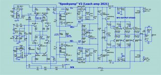
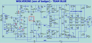
Hi Pete, looking at the design, I have a couple of questions regarding the Input stage. I find the way you have done the cascode and the mirror intriguing:
1. The cascode is rigged to follow the common mode of the differential pair (where R3 and R4 join) by virtue of emiter follower Q8 and R15. But, you divide down the voltage to ~1/2 due to the ratio of R5 and R6. Therefore, the VCE of Q1 and Q2 will be modulated. While this is not the end of the world if Q1 and Q2 are matched, I found this arrangement odd. You can potentially replace R5 with a Zener diode to make the bases of Q6 and Q7 track the common node of the diff pair better.
2. The beta enhancement transistor of the current mirror: Why does the collector of Q5 not go to G2? This one is a bit more concerning.
Referring to attachment:
- The input signal modulates the common mode node of the diff-pair as well as the bases of Q6 and Q7.
- Therefore, the VCE of Q5 is modulated.
- This modulation injects current to the input of the miror via CJC and due to Beta modulation
- This current is input signal dependent
Therefore, you are injecting a distortion current to the input side of the mirror since Beta and CJC are non-linear.
Fix: Tie Q5 collector to G2 via a resistor.
Other problems:
+ Q5 is biased only with base currents. Ths is bad.
- If the current mirror turns off (say amp is slewing where Q1 takes all the current) it will take forever to turn on, and the amp output will stick. Do a large pulse test to see what happens.
- Need a resistor from Q5 emitter to VEE
- Also, if you add this resistor, a capacitor across Q5 VBE to bypass Q5 at HF is a good idea.
Attachments
Last edited:
#1 is what the original slewmaster Wolverine had.
Q5 seems to be more trouble than it is worth.
Remove it.
Both changes are easy.
If anybody made the present board , it could be jumpered out easily.
😱😱
Q5 seems to be more trouble than it is worth.
Remove it.
Both changes are easy.
If anybody made the present board , it could be jumpered out easily.
😱😱
#1 is what the original slewmaster Wolverine had.
Q5 seems to be more trouble than it is worth.
Remove it.
Both changes are easy.
If anybody made the present board , it could be jumpered out easily.
😱😱
Please keep it OS. Make the changes as Sandro suggests

- Home
- Amplifiers
- Solid State
- DIYA store "Wolverine" (Son of Badger) .... suggestions ??