Nice work OS, glad that we can help you out. It was Harry's idea to move C1. Is it possible to post a new Sprint file so we can check the actual file again.# 1 . I took both your idea and Vargas's and integrated them.
C1 is split for us that use normal input caps and is verticle.
Offset has better access , holes with rings are aligned 55mm apart.
This is IPS standard - we have to get this right.
PS - you triggered me , Stuart ... you check it !!
OS
Did you add the positive rail led?
For me having both positive and negative rail leds is mandatory.
Last edited:
Or the "Spooky" IPS red led's - https://www.mouser.com/datasheet/2/678/AV02-1562EN_DS_HLMP-x15x_2018-07-23-1827993.pdf
1.6Vf just like my model...
OS
For LED I suggest:
https://hu.mouser.com/ProductDetail/Vishay-Semiconductors/TLHR4400?qs=W6eMvlWxUPxv3guYUdjVjA%3D%3D
low impedance type.
Sajti
Last edited:
Harry , you check the LED/Cap mult. section .... I redid it for you.
And , Stuart ... the IPS.
Attached file.
Edit - Schema update for LEDs.
OS
And , Stuart ... the IPS.
Attached file.
Edit - Schema update for LEDs.
OS
Attachments
Last edited:
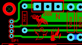
With enough jumping through hoops I've figured out how to import the board file into Diptrace. In Diptrace I can add whatever images you like to the silkscreen, than I can export it back to Sprint with the images in the silkscreen. I figured out how to save them as a macro too, which is good because all of the importing and exporting is butchering the files!
Attachments
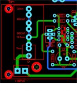
IPS standard -
(Below) spacings for the Wolverine C1 - 34mm is a big as she goes.
JW's solder bridge trick to jump the splits. UMS screw in the way.
To move it right would take up circuit space.
Attached is the standard IPS template. The one I'm using for the Spook !
C1 = 38mm with a 3'rd party IPS. To hit 43mm is possible with the input
euro vertical.
OS
Attachments
With enough jumping through hoops I've figured out how to import the board file into Diptrace. In Diptrace I can add whatever images you like to the silkscreen, than I can export it back to Sprint with the images in the silkscreen. I figured out how to save them as a macro too, which is good because all of the importing and exporting is butchering the files!
Can I have them macro's ?
OS
Sorry I have been away building a router table.🙄
OS - thanks for moving the cap and thanks for adding and moving the LED's!!!
If you have time, can you please reread Sandro's post and comment.
OS - thanks for moving the cap and thanks for adding and moving the LED's!!!
If you have time, can you please reread Sandro's post and comment.
How do I share macros?
ZIP your chosen .LMK's , attach.
Edit , or just the whole .lay6 .... I'll make the macro's from the layout.
OS
If you have something in mind that you would like in the silkscreen let me know. I can make any size too.
Sorry I have been away building a router table.🙄
OS - thanks for moving the cap and thanks for adding and moving the LED's!!!
If you have time, can you please reread Sandro's post and comment.
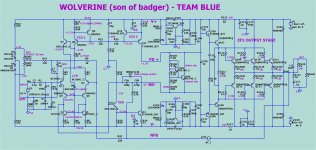
Hi Pete, looking at the design, I have a couple of questions regarding the Input stage. I find the way you have done the cascode and the mirror intriguing:
1. The cascode is rigged to follow the common mode of the differential pair (where R3 and R4 join) by virtue of emiter follower Q8 and R15. But, you divide down the voltage to ~1/2 due to the ratio of R5 and R6. Therefore, the VCE of Q1 and Q2 will be modulated. While this is not the end of the world if Q1 and Q2 are matched, I found this arrangement odd. You can potentially replace R5 with a Zener diode to make the bases of Q6 and Q7 track the common node of the diff pair better.
2. The beta enhancement transistor of the current mirror: Why does the collector of Q5 not go to G2? This one is a bit more concerning.
Referring to attachment:
- The input signal modulates the common mode node of the diff-pair as well as the bases of Q6 and Q7.
- Therefore, the VCE of Q5 is modulated.
- This modulation injects current to the input of the miror via CJC and due to Beta modulation
- This current is input signal dependent
Therefore, you are injecting a distortion current to the input side of the mirror since Beta and CJC are non-linear.
Fix: Tie Q5 collector to G2 via a resistor.
Other problems:
+ Q5 is biased only with base currents. Ths is bad.
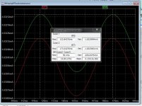
- If the current mirror turns off (say amp is slewing where Q1 takes all the current) it will take forever to turn on, and the amp output will stick. Do a large pulse test to see what happens.
- Need a resistor from Q5 emitter to VEE
- Also, if you add this resistor, a capacitor across Q5 VBE to bypass Q5 at HF is a good idea.
1. He pointed out that it is the common node (of the LTP) that the cascode uses as a reference. Using a 30V zener ( like Wolverine V1) is referencing
the emitter of Q7 (or Q8 C) directly ... -30V.
Using R5 is a distortion mechanism. 🙁
2. Q5 is a good idea if the amp is ideal (not abused).
Too many problems and extra components. The reliability and simplicity
of NO Q5 is worth the lost 1-2ppm. This is such a low power IPS ,
do we need 20 nA mirroring ? (below) is the 200nA "sloppy" basic mirror.
Reducing R20 to 2.2K gets us our 2ppm back ... so does using the proper
BAV20 model ! Pave it over with NFB !!
OS
Attachments
Last edited:
If you have something in mind that you would like in the silkscreen let me know. I can make any size too.
The box from the movie "Hellraiser" (smaller -for the IPS).
Thanks !!
OS
Looks Great OS, You need a outline on layer 0 that surrounds the pcb. This is what the pcb companies use to cut the board to not just sizing the properties of your pcb workspace within sprint layout.Looks purdy , now.
OS
Looks purdy , now.
OS
Why only three output pairs? I think that more pairs would make this amp more universal. I need to drive 4 ohm 550W RMS load. 5-6 pairs would do and those who do not need that much power could use just 2 or 3 output pairs.
cheers,
I believe conforming to the DIY Audio stores UMS spacing limits this to 3 pairs if only one side of the board is used for output devices.
I have the UMS source sheet in front of me. It would be easy to make a
UMS fully modular with the 2 row P/N/P/N. But that is for the future.
They did not want a modular this time .... I snuck one into this. 😀
Nor SMD , but I also snuck that possibility in. 😛
PS - 3 pair MT-200's can do over 300W with this design - I had one.
OS
UMS fully modular with the 2 row P/N/P/N. But that is for the future.
They did not want a modular this time .... I snuck one into this. 😀
Nor SMD , but I also snuck that possibility in. 😛
PS - 3 pair MT-200's can do over 300W with this design - I had one.
OS
Last edited:
- Home
- Amplifiers
- Solid State
- DIYA store "Wolverine" (Son of Badger) .... suggestions ??