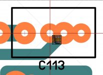
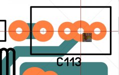
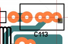
OS do a small tweak to C113 pitch distance 5 mm, 7.5 mm, and 10 mm don't mind my cat Pushi 😛
Attachments
Last edited:
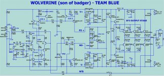
A few little bugs ...
Silk tweaked ,
R25 named /changed to 5K , R23/24 lowered to 22-27K. D4-7 need more current for stable +/- 1.2V reference. (below)
Bourns 3260 side adj. trimpot needed a new Macro.
DRC run , fixed silk on pads errors.
OS
Silk tweaked ,
R25 named /changed to 5K , R23/24 lowered to 22-27K. D4-7 need more current for stable +/- 1.2V reference. (below)
Bourns 3260 side adj. trimpot needed a new Macro.
DRC run , fixed silk on pads errors.
OS
Attachments
Looks good! If nothing changes on the layout by this evening I'll get some prototypes coming.
I see one other bug D3 is not connected on your schematic.
I see one other bug D3 is not connected on your schematic.
D3 is optional and not connected to facilitate simulation. 4148 model , I take
a 4ppm penalty. I lost my "BAV " diode model.
I will note D3 as an option.
Same with C4a/b. A or B jumpered with the other at 47-68pF will be
CMC (miller). C4a +b , 56p/270p to 100p/470p is TMC.
CMC = no R20 .... TMC = R20 - 2.7K.
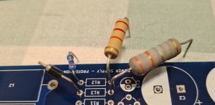
Oh , by the way ... JW - check holes , this was the big complaint on the
Badger. 😱
OS
a 4ppm penalty. I lost my "BAV " diode model.
I will note D3 as an option.
Same with C4a/b. A or B jumpered with the other at 47-68pF will be
CMC (miller). C4a +b , 56p/270p to 100p/470p is TMC.
CMC = no R20 .... TMC = R20 - 2.7K.
Oh , by the way ... JW - check holes , this was the big complaint on the
Badger. 😱
OS
I'll give everything a thorough final check before ordering boards. There will likely be people complaining about 1/2W resistors not fitting throughout the amp, but that's just silly anyways.
Did you have emitter resistors in mind for the output devices or is a pair of generic 3W resistors meant to go there?
Did you have emitter resistors in mind for the output devices or is a pair of generic 3W resistors meant to go there?
I could do the same test on some of the transistors we are looking at for this design if it would be helpful.
That shows the KSC1845 has a Early voltage of about 120. Rco in the quasi-saturation model would be in the very rough ballpark of 214 ohms. The best source I had for making models was DCA75 Pro data from ASTX, but the noise in that data was very high. I used up to 5-point smoothing and still couldn't determine Early voltage on some of the transistors.
I think the available models are good enough for this amp.
I'll give everything a thorough final check before ordering boards. There will likely be people complaining about 1/2W resistors not fitting throughout the amp, but that's just silly anyways.
Did you have emitter resistors in mind for the output devices or is a pair of generic 3W resistors meant to go there?
12 - .5R/Vishay RS02B/M or anal NS (Ayrton-Perry winding) 3 watter's , 14mm body/16mm LS . About 20$$
For cheap , 6 - .22R (KOA BPR58) 15mm LS ceramics. ($3.60)
OS
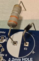
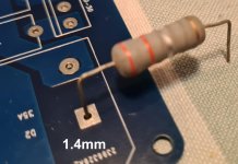
I just did a quick comparison on hole sizes between Diptrace an the Wolverine board. Diptrace 1/4W resistors have a .96mm hole instead of .8mm. Same for the headers. 1/2W and 1W resistors have a 1.17mm hole size instead of 1mm. Emitter resistors are 1.7mm instead of 1.2.
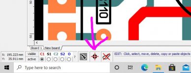
Is there an easy way to alter these in Sprint?
Is there an easy way to alter these in Sprint?
tips and tricks for pitch distance
C113 pitch distance 5 mm, 7.5 mm, 10 mm tips English - YouTube
I forgot to mention that grid capture has to be enable 😛
C113 pitch distance 5 mm, 7.5 mm, 10 mm tips English - YouTube
I forgot to mention that grid capture has to be enable 😛
Attachments
Last edited:
Does that mean diptrace is right ?
Those 2 big resistors (KOA and Vishay) are .8mm +/- .1mm. If those specs are right ... no issue w/ 1mm.
Too big a hole would make populating the board more difficult.
All the small stuff (TO-92 ,1/4w R's,1n914s ,trimmers) , are .62mm (+/- .1mm).
Inductor coils (2mm) , NJW0281 is 1mm +/- .2mm.
TTC004b is .75mm +/- .15mm .... So , .9mm max - I'm at 1mm for those.
I looked at a LOT of datasheets to not repeat the Badger mistakes.
At least 10% over MAX spec. on all.
OS
I've assembled tons of boards with the patterns used in Diptrace and everything fit's nicely. Most of the patterns are drawn from manufacturer's recommended pad sizes. Having too large a hole won't make things harder to assemble, it'll just cause more alloy distortion for the crowd that thinks the blue wire sounds better than the red one.
Emitter resistors are 1.7mm instead of 1.2
@jwilhelm , so what you saying is that you used 1.7mm for emitter resistors tons of times ?
- Home
- Amplifiers
- Solid State
- DIYA store "Wolverine" (Son of Badger) .... suggestions ??