Which raw lcd panel?
Hello all,
I too have read with interest what's going on...
can someone point me to a location where someone has identified a likely (and relatively easy...read "no micro soldering") lcd panel that they have implemented? I want to go the non-projection panel route. As a side note, about ten years ago I built a crt based projection unit using the Delta lenses and three little 4" crt TVs...I have been stewing about the LCD idea for some time and have been knocked out by the last weeks reading of the video threads...great stuff!
George
Monitor choice and mounting
Uvodee,
Thanks for the mounting tip. I too, fortunately, kept the frame intact for future use. Your rig looks great! It's given me a few ideas for my case design.
gkase,
I don't know if your referring to a vga monitor or a tv (composite video in only) monitor. I chose the 5" tv monitor sold at parts express that is typcially used in vehicle installations. The resolution isn't superb, however the price and simplicity of use and installation is. I personally don't have any use for "computer on the wall" so I didn't need that option, my kid uses video game consoles and dvd/vcr only. I intend to use it for tv and dvd/vcr only. We'll see who gets more time on it, me or my kid!😀
for all,
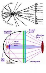
I have modified the optical design I previously posted to this:
light - condenser lense - objective lense - fresnel - fresnel - LCD - fresnel
The condenser lense and objective lense are "butt" up against each other right after the light source. This has greatly increased my brightness. I am in the process of using the previously mentioned "mixing bowl" to work up a reflector. I feel good about it after testing it with lower intensity bulbs. Now I have to cut the hole for the monster MH.
as is, the only screen door effect is on bright white areas or if you walk right up to the wall. and then it only lasts a few seconds as your eyes automatically adjust to it. I think it's as good as I can do with the montitor I'm using.
By the way, as I mentioned before, the condenser and objective came right out of a Delta IV CRT lense at a cost of $4 from a surplus electronics place downtown, so don't write off the Delta IV because of the fish eye problem that was pointed out many moons ago. Just take out the first concave lense and the other lenses are absolutely normal (and big enough to keep you unit from being twelve feet long! Mine looks like it will be about 30" long...)
Keep up the great work, we're getting there.....
Uvodee,
Thanks for the mounting tip. I too, fortunately, kept the frame intact for future use. Your rig looks great! It's given me a few ideas for my case design.
gkase,
I don't know if your referring to a vga monitor or a tv (composite video in only) monitor. I chose the 5" tv monitor sold at parts express that is typcially used in vehicle installations. The resolution isn't superb, however the price and simplicity of use and installation is. I personally don't have any use for "computer on the wall" so I didn't need that option, my kid uses video game consoles and dvd/vcr only. I intend to use it for tv and dvd/vcr only. We'll see who gets more time on it, me or my kid!😀
for all,
I have modified the optical design I previously posted to this:
light - condenser lense - objective lense - fresnel - fresnel - LCD - fresnel
The condenser lense and objective lense are "butt" up against each other right after the light source. This has greatly increased my brightness. I am in the process of using the previously mentioned "mixing bowl" to work up a reflector. I feel good about it after testing it with lower intensity bulbs. Now I have to cut the hole for the monster MH.
as is, the only screen door effect is on bright white areas or if you walk right up to the wall. and then it only lasts a few seconds as your eyes automatically adjust to it. I think it's as good as I can do with the montitor I'm using.
By the way, as I mentioned before, the condenser and objective came right out of a Delta IV CRT lense at a cost of $4 from a surplus electronics place downtown, so don't write off the Delta IV because of the fish eye problem that was pointed out many moons ago. Just take out the first concave lense and the other lenses are absolutely normal (and big enough to keep you unit from being twelve feet long! Mine looks like it will be about 30" long...)
Keep up the great work, we're getting there.....
thumper...a couple of questions
Thanks for the tip on the 5" monitor...are the electronics easy to move out of the way?
Are your fresnels from office supply (8.5x11 page size)?
Thanx
George
Thanks for the tip on the 5" monitor...are the electronics easy to move out of the way?
Are your fresnels from office supply (8.5x11 page size)?
Thanx
George
Hi there,
I don`t understand this...
Why would anyone want to build a home made projector using fresnel lens and going through all this,When you can get a used High quality LCD or CRT projector on Ebay for a song.
I don`t understand this...
Why would anyone want to build a home made projector using fresnel lens and going through all this,When you can get a used High quality LCD or CRT projector on Ebay for a song.
George,
Yes, the electronics were fairly simple to relocate. I simply unscrewed the boards from the back of the backlight and folded them up and screwed them (using the same mounting holes) flat against the board I mounted the screen on (Kind of made my own frame out of 1/4" sheeting. Kind of like opening a book and screwing it's covers down to the table. The backlight then slid right out of the frame. The parts express part # is 205-013 and the power supply that I'm using is #120-532 (it's a pyramid regulated power supply that I'll also use to power my 12v fan).
The fresnels are plastic 81/2" X 11" from Staples. I got a picture good enough to sit and watch Star Ship Troopers last night ( I still can't believe that's my favorite movie. My wife laughs everytime I watch it...). I'm going to keep my eyes open for glass fresnels to increase the focus and brightness even more though. I imagine glass fresnels with very fine grooving will be quite an improvement, but rather than buying them I'll wait till I can salvage them somehow and from somewhere. For now the plastics work fine.
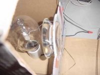
Still waiting to cut open the "mixing bowl" to create the reflector. The shape, size and finish look perfect. I got it at "Big Lots", a close-out type store here in Florida. I was "Dad" tonight and had to hang up my "Mad Scientist lab coat" so I didn't get to it yet. Maybe this weekend, the kids should come first.
BenY,
My father used to tell me, "no one takes time to appreciate their own work any more, therefore there's no pride in their work. It's just something they had to do..." I take pride in what I build, it gives me a sense of satisfaction and continues to build my confidence and self-esteem. I try to pass this on to my kid, considering the world we live in I figure she can use all the help she can get.
Enough of that already, It's also a whole lot of fun!
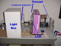
I will ad some pics ASAP. I have it set up on the project table so you should be able to get a good idea of the optical sequence and how I'll have to put it all to together. I've got some pretty good ideas for focusing and what not. My brother is a skilled cabinet maker so I'll definitely be calling in on him for some help. It helps to "know people".😉
Talk at ya;
Yes, the electronics were fairly simple to relocate. I simply unscrewed the boards from the back of the backlight and folded them up and screwed them (using the same mounting holes) flat against the board I mounted the screen on (Kind of made my own frame out of 1/4" sheeting. Kind of like opening a book and screwing it's covers down to the table. The backlight then slid right out of the frame. The parts express part # is 205-013 and the power supply that I'm using is #120-532 (it's a pyramid regulated power supply that I'll also use to power my 12v fan).
The fresnels are plastic 81/2" X 11" from Staples. I got a picture good enough to sit and watch Star Ship Troopers last night ( I still can't believe that's my favorite movie. My wife laughs everytime I watch it...). I'm going to keep my eyes open for glass fresnels to increase the focus and brightness even more though. I imagine glass fresnels with very fine grooving will be quite an improvement, but rather than buying them I'll wait till I can salvage them somehow and from somewhere. For now the plastics work fine.
Still waiting to cut open the "mixing bowl" to create the reflector. The shape, size and finish look perfect. I got it at "Big Lots", a close-out type store here in Florida. I was "Dad" tonight and had to hang up my "Mad Scientist lab coat" so I didn't get to it yet. Maybe this weekend, the kids should come first.
BenY,
My father used to tell me, "no one takes time to appreciate their own work any more, therefore there's no pride in their work. It's just something they had to do..." I take pride in what I build, it gives me a sense of satisfaction and continues to build my confidence and self-esteem. I try to pass this on to my kid, considering the world we live in I figure she can use all the help she can get.
Enough of that already, It's also a whole lot of fun!
I will ad some pics ASAP. I have it set up on the project table so you should be able to get a good idea of the optical sequence and how I'll have to put it all to together. I've got some pretty good ideas for focusing and what not. My brother is a skilled cabinet maker so I'll definitely be calling in on him for some help. It helps to "know people".😉
Talk at ya;
beny,
yes you could probobly find a used projector for a decent price, but i bet most people don't want to spend $400 on a replacement light every 2000 hours. many of the metal halide bulbs that we use can last up to 20000 hours and cost $40.
gaff
yes you could probobly find a used projector for a decent price, but i bet most people don't want to spend $400 on a replacement light every 2000 hours. many of the metal halide bulbs that we use can last up to 20000 hours and cost $40.
gaff
the main reasons why i jumped in on this is because it's simply cool! For a low price you can build yourself a pretty good quality lcd projector.
I haven't been able to purchase more parts than the lcd panel (car problems and stuff) but when i have the cash i can't wait to get back on the bandwagon.
it's the whole "I built it myself" thing... it would feel great to build my own projector, would be cool, would be creative, would last longer, etc... 😀
anywho, i gotta finish my windows reinstall... 🙁
lcd mounting
well gkase
i wasn't that lucky with my lcd compared to all the others here in this forum.
my screen had 3 flex cables north, south and east of it so only one was kept intact, the others i had to prolong ( i hope this is proper english) with extra flex cable .. Boy boy, was this a night mare or what there were 2 cable formats
one had 10 connections and was 11.15 mm (0.5 mm conn)
the other had 20 connections and was 16 mm (0.8 mm conn)
rookie that i am in the US in took me a day before i had located the supplier/distributor and allthoug digikey sent me the connectors and one of the cables, fujicard did it because i guess thesalesperson took a few moments of his break to help me... when i told him i only needed one cable from him he almost broke his neck from laughing i think! he's more used to dealing with 100.000 pieces i guess!
I will post some pics of this lcd positionning i did tomorrow i hope.
no reply on Fibonacci ??? interesting!
Jean-Pierre
i have bulit this projector even better than the plans and its like this it seems to project well when your hand are a picture is under it but withe lcd it just dont cut it ,,,with the lcd it playstation screen it looks better withe the light off useing the light from the lcd all in all so far you will get a head ake rfrom trying to see the picture its there but its just not there hope this helps im trying some new things ill post in awhile
......jamie
......jamie
BenY said:Hi there,
I don`t understand this...
Why would anyone want to build a home made projector using fresnel lens and going through all this,When you can get a used High quality LCD or CRT projector on Ebay for a song.
For some of us, its a reason to learn something. I've already learned more about optics than ever before. Several years of doing my own B&W film processing didn't force me to really understand what was going on inside the boxes I used, but this does.
Remember Heathkit? DIY is cool!
Re: 65 watters
Hey what's that big ball of wires behind your lamp housings?
I have been experimenting with one 65watter and i barely get anything but a dim image. Worse than what i have with my 1953 300w projector bulb. Will adding a second really make a big enough difference? Did you refract or reflect the light in any way. Did you use Frenzels in front or a or Mirror behind?
Thanks for the inspirational pics.
Now i need more! More ! MORE !
Paul
Re: diagram of projector
I have had success using a fresnel as a projection (after LCD) lens. The clarity was much better than i expected and there was no noticeable distortion like i had with my glass fish eyes. Now I'm trying to find a way to increase my light output. Maybe then i will notice problems but for now the cheap staples lens is working very well.
Paul - The Nephilum
thumper said:This is how simple the design I'm trying out is. I have no idea how it's going to work once I get the housing built and actually add a brushed aluminum reflector behind the bulb.
I have had success using a fresnel as a projection (after LCD) lens. The clarity was much better than i expected and there was no noticeable distortion like i had with my glass fish eyes. Now I'm trying to find a way to increase my light output. Maybe then i will notice problems but for now the cheap staples lens is working very well.
Paul - The Nephilum
FluoreX
Hey G!
Not to step on unvodee's toes but i can tell you what light he's using. I've spent a little time trying with one lamp but that wasn't bright enough. His system has two.
It is a FluoreX bulb sold by Lights of America as a Fluorescent Work Light. Its 65w and they claim its output equals a 500w halogen. It IS bright and i can't argue that it wouldn't make a great work light.
It is relatively cool (acually cold compared to some of the projection lamps i've tried). It is so white that it makes my walls look yellow but it does not project a beam. I'm finding it hard to focus all the light onto the frensel & OHP Panel. It seems uvodee has found a way to make it work.
I got mine at Wal-Mart and I've read that they are also available at home depot and other DIY home improvement places.
For more info search our forums for Fluorex.
Mine was $24.95 USD
Hope that helps!
Paul - The Nephilum
CAD said:@uvodee
What kind of lamp is it - and where can i buy it?
greetz
CAD
Hey G!
Not to step on unvodee's toes but i can tell you what light he's using. I've spent a little time trying with one lamp but that wasn't bright enough. His system has two.
It is a FluoreX bulb sold by Lights of America as a Fluorescent Work Light. Its 65w and they claim its output equals a 500w halogen. It IS bright and i can't argue that it wouldn't make a great work light.
It is relatively cool (acually cold compared to some of the projection lamps i've tried). It is so white that it makes my walls look yellow but it does not project a beam. I'm finding it hard to focus all the light onto the frensel & OHP Panel. It seems uvodee has found a way to make it work.
I got mine at Wal-Mart and I've read that they are also available at home depot and other DIY home improvement places.
For more info search our forums for Fluorex.
Mine was $24.95 USD
Hope that helps!
Paul - The Nephilum
hi im back and broke
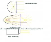
ive notice there are two ways that light should travel from the light source setup for even light. parallel rays from the bulb and reflector, or ray evenly spread from the point of source(yes the ray can be reflected as long as they reflect back in the same direction they came from "the point of source") but the thing is we cant go with both because they use different lens setups. i might be wrong but i doubt it. see the pic's below
i just thought about it and im wrong on one part .with a parabolic reflector its not posible to get even spread parallel rays.so basicly
lasers dose parallel even rays, and parabolic reflectors do both parallel and raysfrom point of source, and 1/2 sphears reflector setup dose evenly spread light from point of source. ill put some picture exsamples in a little bit to explain the two way that would work and the resond why parabolic might not be good for even rays of light. i still might be wrong on this so tell me if im wrong.
Attachments
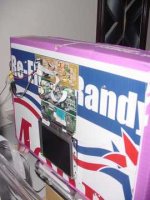
LCD Mounting
The LCD mounting (temporary but you get the message). The boards simply folded up (see the triple ribbon cable a the top of the screen connecting the screen and the green board). The three boards have holes in them to run small screws through and secure it to the mounting board.
The LCD mounting (temporary but you get the message). The boards simply folded up (see the triple ribbon cable a the top of the screen connecting the screen and the green board). The three boards have holes in them to run small screws through and secure it to the mounting board.
Attachments
Picture
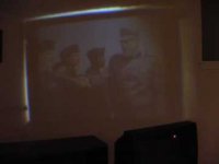
I TOTALLY agree with everyone so far who has said "digital cameras were NOT meant for dark or low light conditions!!!!!!!!
This is the best I could get. I wouldn't want to tell my family they had to watch it as a primary right now, but I have watched it two nights in a row with no discomfort. The dark area at the top right is a piece of paper I was using to try and block some of the ambient light. The white at the edge of the picture is the poor temporary framing job I did around the LCD panel.
I really feel that the reflector will help with the brightness. Even if it doesn't though, I've at least proven how to do this type of setup, and just replace where I have a 250watt with a 400watt. I just don't feel inclined to go out and spend another $70 or so for a new ballast and bulb until I've exhausted all other means.
The other types of setups have their own way of doing it and who knows, may very well look a whole lot better.... The whole issue boils down to "how much you wanna pay?" High cost, high quality parts will produce a higher quality picture. I think that with ongoing tinkering someone will find just the right combination of locally available parts to make it all work just right.
I don't think this is too bad for a bunch of stuff propped up with coat hangers and cardboard. I will begin on the permanent housing as soon as I'm happy with some kind of results from a reflector.
Attachments
- Home
- General Interest
- Everything Else
- The Moving Image
- DIY Projectors
- DIY Video Projector Part II