It is very likely as Ben said since the ref voltages are the same on both boards.
It takes me 3-4 tries on x” “ regs to get the correct ref voltages.
It takes me 3-4 tries on x” “ regs to get the correct ref voltages.
Hi Ben and Greg,It's a very good chance that the TL431, X2 and X3 are not working. They can be damaged by too much heat during soldering. A quick way to test them is to measure their Vref which should be 2.5V if they are functioning properly. Vref is measured between the Ref pin and Anode.
Thank you for your reply.
As I mentioned in above post the measured voltages on the TL431 is: 0V over X2, -19V over X3, +4V over x1.
I already changed X2 on both boards but the voltages do not change. I am wondering if another component may be broken instead of x2.
I am pretty sure I have not soldered too long or to hot (350degC)
But before I destroy the pcb and good components by replacing them I am curious if anybody can determine the broken component on these measurements.
Is it possible that a bad soldering on c13 causes this problem?
Hi All,
I have found the mistake! I accedently soldered R29 on the spot of C29! In this way -5V does not get any power.
now I measure:
pin 26=-5v
pin 28=+4,65v
pin 15=-15v
Is the +4,65v within the specs?
I have found the mistake! I accedently soldered R29 on the spot of C29! In this way -5V does not get any power.
now I measure:
pin 26=-5v
pin 28=+4,65v
pin 15=-15v
Is the +4,65v within the specs?
Your V- supplies are good now.
The +4.65V is a bit low. R18 (1K) and R20 (1K) at X1 (TL431) control the V+ voltage, so check R18 and R20 for correct value and good solder joints. If the TL431 is working and R18 and R20 are correct, the voltage output should be 5V or very close to it. You can also check the values of R16, R17, and R21 which set the output voltage of the LM317 (V1) pre-regulator that feeds X1. You can also measure the voltage output of V1. That voltage should be 28V or so.
If all measure good, then check that the TL431 Vref is 2.5V.
Edit: The LM317 circuit should be okay as it also provides voltage to the V- regulators and you are getting proper V- voltages. The issue is most likely within the +5V TL431 circuit.
Last edited:

Hi Ben,Your V- supplies are good now.
The +4.65V is a bit low. R18 (1K) and R20 (1K) at X1 (TL431) control the V+ voltage, so check R18 and R20 for correct value and good solder joints. If the TL431 is working and R18 and R20 are correct, the voltage output should be 5V or very close to it. You can also check the values of R16, R17, and R21 which set the output voltage of the LM317 (V1) pre-regulator that feeds X1. You can also measure the voltage output of V1. That voltage should be 28V or so.
If all measure good, then check that the TL431 Vref is 2.5V.
Edit: The LM317 circuit should be okay as it also provides voltage to the V- regulators and you are getting proper V- voltages. The issue is most likely within the +5V TL431 circuit.
I measure lower voltage over R20 in comparison to R25, R30 (measured on both pcb’s):
R20=2,35v (and 2,31v on second board)
R25=2,5v (and 2,5v)
R30=2,49v (and 2,48v)
R18 measures 2,36v (and 2,32v)
Because both boards measure the same I think it is not an incidental issue like a bad soldering.
Is it possible due to tolerances on x1:TL431?
By the way: R21 is lowered to 4k7. I do not know if this has any influence.
voltage attached to the board is 26,5v
Attachments
Your R21 is incorrect. Build it according to the schematic (5K1) and the voltage should be 5V.
Why did you lower it to 4K7?
Why did you lower it to 4K7?
https://www.diyaudio.com/community/threads/diy-tda1541a-pcb-d3.328060/post-6705696Your R21 is incorrect. Build it according to the schematic (5K1) and the voltage should be 5V.
Why did you lower it to 4K7?
Whoops, sorry, I misread the resistor designations and assumed that R21 was at the TL431. R21 is at the LM317 and does not affect the voltage out of the TL431.
The resistor values that you need to check are R18 and R20 as I mentioned in post #1224:
The values of R18 and R20 need to be confirmed - 1K Ohm for each resistor. This should get the TL431 to output 5V.
The weird thing is that I calculated the TL431 voltage using the LM317 resistor values and the voltage was 2.63V, which my mind then thought 4.63V. It's too early in the morning for me.🙂
The resistor values that you need to check are R18 and R20 as I mentioned in post #1224:
Your V- supplies are good now.
The +4.65V is a bit low. R18 (1K) and R20 (1K) at X1 (TL431) control the V+ voltage, so check R18 and R20 for correct value and good solder joints. If the TL431 is working and R18 and R20 are correct, the voltage output should be 5V or very close to it. You can also check the values of R16, R17, and R21 which set the output voltage of the LM317 (V1) pre-regulator that feeds X1. You can also measure the voltage output of V1. That voltage should be 28V or so.
If all measure good, then check that the TL431 Vref is 2.5V.
Edit: The LM317 circuit should be okay as it also provides voltage to the V- regulators and you are getting proper V- voltages. The issue is most likely within the +5V TL431 circuit.
The values of R18 and R20 need to be confirmed - 1K Ohm for each resistor. This should get the TL431 to output 5V.
The weird thing is that I calculated the TL431 voltage using the LM317 resistor values and the voltage was 2.63V, which my mind then thought 4.63V. It's too early in the morning for me.🙂
Last edited:
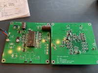
Strange thing: I cleaned the board from solder resin with alcohol and inserted the TDA dac chips and now all power points measure perfectly well!
It annoys me when I cannot understand what is happening 😕 Maybe some of the solder paste made a path parallel to one of the resistors? Anyway, all is working and I am happy👌🏻👍🏻
It annoys me when I cannot understand what is happening 😕 Maybe some of the solder paste made a path parallel to one of the resistors? Anyway, all is working and I am happy👌🏻👍🏻
Attachments


Hi Supersurfer, are you using a UC conditioner on the 5V line, does it have a big effect on the sound?
I believe that the +5V is just for the I2S input level shifting circuit so perhaps not the first place to splash cash.
I use a 1s lipo battery (5Ah) to run the i2s and USB, sounds fantastic on battery power.
This dac is so enjoyable to listen to that after several years I of listening I it’s don’t feel the need to build anything else (dac wise)
This dac is so enjoyable to listen to that after several years I of listening I it’s don’t feel the need to build anything else (dac wise)
I also have never heard any dac that is as musical and analog sounding as my D3 in balanced mode. I listened a year to two boards and since a month I have 4 boards running and it is even better.
I do try to find a better dac and have not succeeded until now, so my conclusion is that it is a very good sounding piece of gear!
I do try to find a better dac and have not succeeded until now, so my conclusion is that it is a very good sounding piece of gear!
I also enjoy the D3 for a long time now. Thank you once again to Ryan for all the work he put into this DAC. To be honest, most of the mods i made to this DAC were removed again, because the difference was not big enough for me. What stayed is my battery PSU with LifePo4 Batteries. This was really a game changer for this DAC. It sound even better now. Of course 22 LifePo4s are a bit overkill, but i wanted to have all the voltages battery based and I receive the batteries very, very cheap... The only thing I didnt try was the supercapacitors, perhaps I will try it in the next months.
Wrt supercaps, I would suggest focusing in +5 -5V. There are inexpensive little 5.2V caps that will give you a sense if anything is to be gained. In my case there was, but I run D1 with a PS of my own design so it may or may not be comparable.
I have 4 PCBs now travelling to me. My next challange is to get hold of the 4 TDA 1541A chips, any ideas guys please let me know. I am searching eBay for CD players with these and do have 1 player now.
- Home
- Group Buys
- DIY TDA1541A PCB "D3"