Hi Supersurfer, D3 is still improving already has about 80 hours of listening, I would like to replace the DIR 9001, what would you recommend for the parts?Hi,
Good to see your report: have fun listening to this awesome DAC design!
I do not use receiver chips, spdif protocol and receivers are a bottle neck in the chain; introducing jitter. If you are using a source that only delivers spdif output I cannot advise of alternatives.Hi Supersurfer, D3 is still improving already has about 80 hours of listening, I would like to replace the DIR 9001, what would you recommend for the parts?
I use a streamer build with an Allo usbridge signature with a compute module, through the header you get a direct I2S signal that goes through a fifopi and reclocker, before it enters the I2S-sim pcb.
I use an Allo Usbridge Signature too. I first tried Ian's FifoPi with NDK clocks, full battery supply and I2S into the D3, but I've since tried a JLSounds USB to I2S board configured in simultaneous mode which I prefer.
Ryan and IanCanada both do a I2S to simultaneous conversion board, which I've yet to try, but my ears are convinced simultaneous is the way to go to get the most out of the TDA1541A. See
https://www.diyaudio.com/community/...ate-nos-dac-using-tda1541a.79452/post-5491428
Ryan and IanCanada both do a I2S to simultaneous conversion board, which I've yet to try, but my ears are convinced simultaneous is the way to go to get the most out of the TDA1541A. See
https://www.diyaudio.com/community/...ate-nos-dac-using-tda1541a.79452/post-5491428
Simultanous is best for TDA1541A dacs; splitting the L-R data outside the dac chip will improve jitter level. The I2S-PCM board from Ryanj seems to be better than the one from Ian.I use an Allo Usbridge Signature too. I first tried Ian's FifoPi with NDK clocks, full battery supply and I2S into the D3, but I've since tried a JLSounds USB to I2S board configured in simultaneous mode which I prefer.
Ryan and IanCanada both do a I2S to simultaneous conversion board, which I've yet to try, but my ears are convinced simultaneous is the way to go to get the most out of the TDA1541A. See
https://www.diyaudio.com/community/...ate-nos-dac-using-tda1541a.79452/post-5491428
Hi, I added 2 supercaps 10F in series to the 5V lines and the boards work perfectly, I charge in max 3 minutes.Hi Walter,
I couldn't get the simulation working with such a large capacitance so im not totally sure how it will behave. But no matter what the CCS in the path of the zener string will always stay constant at 135mA. So if anything while the caps charge up CC1 will have a higher voltage drop across it so will have to dissipate more power during startup. Might be enough to put a heat sink on CC1. (Try at your own risk.)
I have 25 D3 PCBs left.
Attachments

Can you go from 'USB' direct to Philips simdata mode and bypass I2S altogether?.
Is that what the JL Sounds solution allows for (no I2S to/from conversion)?.
Cheers
Is that what the JL Sounds solution allows for (no I2S to/from conversion)?.
Cheers
In theory this would be possible. You only need to find a USB converter that puts out a SIM data stream.
Exactly how the JLSounds gets to simultaneous output I'm not sure. The XMOS XU208 is the USB front end. A quick scan of the datasheet looks like it isn't tied to any defined output logic, so I'm guessing that's handled by the microcontroller. The output is galvanically isolated and reclocked. So my best guess is yes, no I2S along the way 🙂 ask JLSounds, Luyben is very helpful.Can you go from 'USB' direct to Philips simdata mode and bypass I2S altogether?.
Is that what the JL Sounds solution allows for (no I2S to/from conversion)?.
Cheers
All I know is with two decent power supplies, one for dirty side, one for clean side (no power taken from the USB bus), it sounds great with the D3 and it's not expensive either.
Hi All,
I have decided to build a D3 DAC and wanted to consolidate most of the data I have been extracting form this thread. I confess I did not read every single message but used the search functionality extensively before asking.
I have an old JLSounds USB2I2S board plus buffer plus oscillator. From what I have read I can use this to feed directly two D3 boards in sim mode.
I also have a good stack of Salas (both HV and LV).
I intend to use a Thorsten Gomez totempole valve output stage.
What are the advises for such a configuration? For what I understand I can feed two D3 boards in sim mode directly from the jlsounds with equivalent results than using Ryan's sim board. And what is a CMx board (apologies for asking very dumb questions but I have been roaming this thread, the forum and the whole internet and only found references to connectors).
Does it make sense to use the JLSounds buffer (I am not even sure it will work in sim mode).
My background is on tube builds, dac modding and TH solid state amplifiers boards. Managed to work on a couple of very tricky smd projects with Wolfson DAC boards with my SP200 soldering station but have limited experience with that. Have 500F tips thou but not very small (2.5 mm) as small tips at low temp do not work very well especially on big thermal mass pads.
Also, do you have suggestion on good flux for this work, excluding the one everyone is raving about and only available in US from esoteric sources (I am based in UK)?
Many thanks for whoever will spend hir time to help me.
Antonio
Hi Antonio,Hi All,
I have decided to build a D3 DAC and wanted to consolidate most of the data I have been extracting form this thread. I confess I did not read every single message but used the search functionality extensively before asking.
I have an old JLSounds USB2I2S board plus buffer plus oscillator. From what I have read I can use this to feed directly two D3 boards in sim mode.
I also have a good stack of Salas (both HV and LV).
I intend to use a Thorsten Gomez totempole valve output stage.
What are the advises for such a configuration? For what I understand I can feed two D3 boards in sim mode directly from the jlsounds with equivalent results than using Ryan's sim board. And what is a CMx board (apologies for asking very dumb questions but I have been roaming this thread, the forum and the whole internet and only found references to connectors).
Does it make sense to use the JLSounds buffer (I am not even sure it will work in sim mode).
My background is on tube builds, dac modding and TH solid state amplifiers boards. Managed to work on a couple of very tricky smd projects with Wolfson DAC boards with my SP200 soldering station but have limited experience with that. Have 500F tips thou but not very small (2.5 mm) as small tips at low temp do not work very well especially on big thermal mass pads.
Also, do you have suggestion on good flux for this work, excluding the one everyone is raving about and only available in US from esoteric sources (I am based in UK)?
Many thanks for whoever will spend hir time to help me.
Antonio
Sorry for my slow response, just recently we relocated and have not had time for Audio stuff.
The CMx is a capacitance multiplier in both the negative and positive rails, nothing special but does a decent job at filtering ripple and noise.
Yes I have PCBs in stock, I just have to find what box I put them in, so please bare with me.
I haven't had experience with the JLsounds usb2i2s board, but I think a few people were using it with good results.
Ryan
Thanks, Ryan.Hi Antonio,
Sorry for my slow response, just recently we relocated and have not had time for Audio stuff.
The CMx is a capacitance multiplier in both the negative and positive rails, nothing special but does a decent job at filtering ripple and noise.
Yes I have PCBs in stock, I just have to find what box I put them in, so please bare with me.
I haven't had experience with the JLsounds usb2i2s board, but I think a few people were using it with good results.
Ryan
No hurry, I perfectly understand the situation and can wait until you have sorted more important things.
All the best for your new home!
Antonio
Hi peppennino. Yes I have boards left, you can find the order form on the opening post of this thread.Hi Ryan, is it possible to buy your boards?
Thanks Antonio! Ill message you shortly.Thanks, Ryan.
No hurry, I perfectly understand the situation and can wait until you have sorted more important things.
All the best for your new home!
Antonio
Hi Ryan, I just now realized you sent me a paypal request for payment the day after your last message. I was kind of expecting a message here instead.Thanks Antonio! Ill message you shortly.
That is settled now.
Many thanks,
Antonio
Sorry for the confusion!Hi Ryan, I just now realized you sent me a paypal request for payment the day after your last message. I was kind of expecting a message here instead.
That is settled now.
Many thanks,
Antonio
Payment received.
I'll send your package out this week.
Thanks.
Has anyone actually checked the Dem is running at 50hz with a 1uf capacitor.
As Ecdesigns in a couple of posts one of them being 8023 about having a capacitor as high as 2.2uf and up to 470uf for the 14 electrolytics.
https://www.diyaudio.com/community/...ltimate-nos-dac-using-tda1541a.79452/page-402
As Ecdesigns in a couple of posts one of them being 8023 about having a capacitor as high as 2.2uf and up to 470uf for the 14 electrolytics.
https://www.diyaudio.com/community/...ltimate-nos-dac-using-tda1541a.79452/page-402
Hi @ryanj,
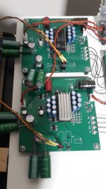
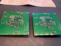
I have finally found some time to build 2 extra D3 boards. And I am running into a power supply issue (again).
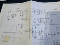
I have soldered the power supply components as in the manual from @ggetzoff and measured the following voltages:
at pin 26=0V
at pin 28=+4V
at pin 15=-19V
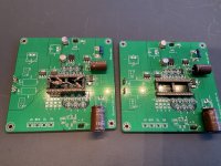
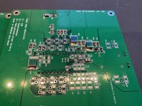
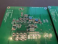
I measure 0V over X2 (see picture), -19V over X3, 4V over x1.
I measure exactly the same on both boards. My idea is that x2 must be defective so I replaced them together with c14 on both boards but the issue remains.
Just to be sure I also soldered in most of the other power supply components but the issue remains.
Can you or anybody else help me out here?
I have finally found some time to build 2 extra D3 boards. And I am running into a power supply issue (again).
I have soldered the power supply components as in the manual from @ggetzoff and measured the following voltages:
at pin 26=0V
at pin 28=+4V
at pin 15=-19V
I measure 0V over X2 (see picture), -19V over X3, 4V over x1.
I measure exactly the same on both boards. My idea is that x2 must be defective so I replaced them together with c14 on both boards but the issue remains.
Just to be sure I also soldered in most of the other power supply components but the issue remains.
Can you or anybody else help me out here?
Attachments
-
 5DB4A40C-CD80-4ABD-A7FF-52A770AA276C.jpeg574.6 KB · Views: 238
 -
 20C5C90F-C20A-4B24-95A7-F5E34144AD25.jpeg594.9 KB · Views: 246
 -
 DCF62792-BC1D-4C7E-95BB-EFC676CAD842.jpeg574.4 KB · Views: 257
 -
 AD29BCB5-924D-413A-8E4C-081CF29A4ED3.jpeg434.6 KB · Views: 222
 -
 7DFD8740-2305-44A2-AD8A-538F3988EB57.jpeg583.3 KB · Views: 222
It's a very good chance that the TL431, X2 and X3 are not working. They can be damaged by too much heat during soldering. A quick way to test them is to measure their Vref which should be 2.5V if they are functioning properly. Vref is measured between the Ref pin and Anode.
Attachments

- Home
- Group Buys
- DIY TDA1541A PCB "D3"