That looks great!
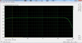
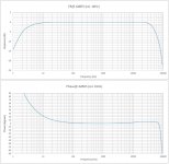
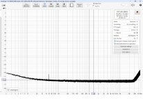
Any chance of seeing the frequency response with 192kHz sample rate?
Here you are.
Attachments
The high gain preamp
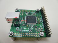
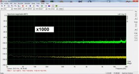
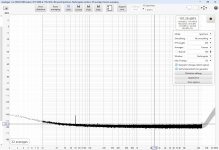
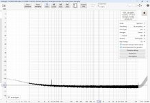
As already said this is Rod Elliott's P158. All info is there. The layout is mine, hopefully performing close to the original. It applies only to the left input and it is SE. So, unbal input mode should be selected to make it work. Also the input of this preamp is DC coupled, no input capacitor. It is engaged with NEC UC2-4,5NU relays. They are supplied from the unused usb Vbus. For the DIYINHK I2S converter here is an easy hack: close to the usb port there is a provision for a three pin connector. I guess this was for selecting usb or external psu with a jumper. Conveniently, this can be used to take the Vbus and also to power the module with 3,3V using a proper gauge wire. See pic. Attached noise floor measurements with input floating free and attenuator full open. The orange line is the basic floor of the input for reference.
As already said this is Rod Elliott's P158. All info is there. The layout is mine, hopefully performing close to the original. It applies only to the left input and it is SE. So, unbal input mode should be selected to make it work. Also the input of this preamp is DC coupled, no input capacitor. It is engaged with NEC UC2-4,5NU relays. They are supplied from the unused usb Vbus. For the DIYINHK I2S converter here is an easy hack: close to the usb port there is a provision for a three pin connector. I guess this was for selecting usb or external psu with a jumper. Conveniently, this can be used to take the Vbus and also to power the module with 3,3V using a proper gauge wire. See pic. Attached noise floor measurements with input floating free and attenuator full open. The orange line is the basic floor of the input for reference.
Attachments
Vcom comes from a voltage divider to a DC buffer. Do not use the Vcom from the CS4272 for this job. It doesn't like it at all! Bypass this with 1μF and leave it alone.
Hi, I am following your design to make a similar thing. I can't understand why you emphasis not to use Vcom from CS4272. Is it due to noise issue or driving capability? Will a DC buffer be helpful?
Hi,
It's just an empirical finding. On an early version of my pcb, the DC buffer could take either from a voltage divider or from Vcom with a jumper. Vcom introduced noise. You will need a buffer but don't take it to Vcom.
Good luck with your project! Keep us updated!
It's just an empirical finding. On an early version of my pcb, the DC buffer could take either from a voltage divider or from Vcom with a jumper. Vcom introduced noise. You will need a buffer but don't take it to Vcom.
Good luck with your project! Keep us updated!
I just came across this thread, having a similar interest in low-level distortion measurements. I have mostly been following and participating in the thread titled "Howto - Distortion Measurements with REW" here.
I have been using an old EMU 0404 interface for my experiments.
One thing that occurred to me is that you could improve on the differential stage by using Bill Whitlock's very clever (and patented) bootstrap technique to greatly increase the input impedance and CMRR of the stage. The EMU used this technique.
See the attached schematic - the technique sums the common-mode signal at the outputs of the input buffer pair and feeds it back into the inputs. Of course, component matching and trimming are critical to making this work properly.
Rod Elliott posted an excellent article here, mainly written by Bill Whitlock, which covers balanced systems in general.
Cheers
Attachments
Thanks for the links! No doubt the input buffer scheme I used is not the very best out there. But I feel it already took the digital converter to its limits. Lower THD+N perhaps would be good only to reveal its weakness.
Regarding input impedance and CMRR, I also tried another scheme based on an INA, AD8130 in particular. Unlike the majority of INAs, this one has an exceptional CMRR at the MHz region together with very high Zin. It was the only thing that accepted 100k potensiometer wired in "U" shape without sweat. The problem was its poor THD+N, nowhere close to OPA1656. Diff in/SE out of this buffer does not take advantage of the differential input of the ADC driver OPA1632 which sets the limits more or less. All that said, the scheme you posted maybe address these issues. Good to know there is an all opamp version!
Regarding input impedance and CMRR, I also tried another scheme based on an INA, AD8130 in particular. Unlike the majority of INAs, this one has an exceptional CMRR at the MHz region together with very high Zin. It was the only thing that accepted 100k potensiometer wired in "U" shape without sweat. The problem was its poor THD+N, nowhere close to OPA1656. Diff in/SE out of this buffer does not take advantage of the differential input of the ADC driver OPA1632 which sets the limits more or less. All that said, the scheme you posted maybe address these issues. Good to know there is an all opamp version!

Actually, there is an IC version of Whitlock's scheme. It is made by thatcorp.com. Whitlock licensed the patent to them. Check out the 1200 series.
I have not tried this (yet) but I am thinking you could build an all opamp version of this with, say, OPA1656s and VERY carefully tweaked low noise resistors.
Cheers
I have not tried this (yet) but I am thinking you could build an all opamp version of this with, say, OPA1656s and VERY carefully tweaked low noise resistors.
Cheers
On a quick datasheet comparison, the THAT chip seems superior to AD8130. I was looking for something like this for another project, thanks! As for this project, I still have my reservations. The opamps have much lower distortion and CMRR of OPA1632 is very good as well. The only thing that the THAT could do better is very high Zin, but as is now it's 100k SE, 200k diff.
I was amazed to see an amateur courageous and capable enough to try diying a soundcard!
After reading this thread, I was intringued by the low THD numbers achieved at 0dBFS.
It so happens that I live in the same city with Magic Bus.
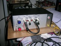
I PMed Magic Bus. We had a coffee meeting (same benigh live experience as that through reading his posts) and I was honoured to have his soundcard on my test bench for a while.
It's operation versatility is superb. It has everything one needs to test anything, low and high output level devices.
DAC: 0dBFS max out:3.736Vrms
ADC (x1 gain, no input attenuation): 1.5137Vrms for 0dBFS
I confined myself to a few tests and only SE loopback x1 gain
George
After reading this thread, I was intringued by the low THD numbers achieved at 0dBFS.
It so happens that I live in the same city with Magic Bus.
I PMed Magic Bus. We had a coffee meeting (same benigh live experience as that through reading his posts) and I was honoured to have his soundcard on my test bench for a while.
It's operation versatility is superb. It has everything one needs to test anything, low and high output level devices.
DAC: 0dBFS max out:3.736Vrms
ADC (x1 gain, no input attenuation): 1.5137Vrms for 0dBFS
I confined myself to a few tests and only SE loopback x1 gain
George
Attachments
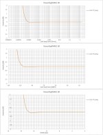
0.5dB gain linearity goes to 17bits (good for 16bit data).
Jitter test is very clean.
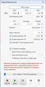
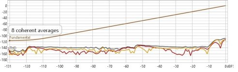
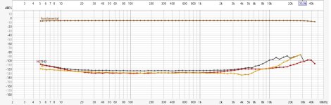
step freq THD@-6dBFS very good
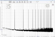
Multitone test is clean down to 21-22 bits, very good.
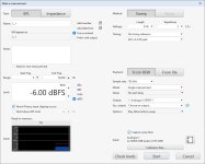
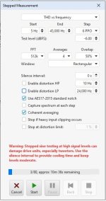
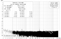
step level THD @1kHz very good
Jitter test is very clean.
step freq THD@-6dBFS very good
Multitone test is clean down to 21-22 bits, very good.
step level THD @1kHz very good
Attachments
-
 level step settings.jpg56.9 KB · Views: 128
 -
 step level.jpg51.1 KB · Views: 130
 -
 multitone settings.jpg90.7 KB · Views: 124
 -
 multitone.jpg271.9 KB · Views: 122
 -
 step freq settings.jpg55 KB · Views: 120
 -
 step freq@48k.jpg136.6 KB · Views: 119
 -
 J-test.jpg216.1 KB · Views: 136
 -
 linearity SR 44k1.jpg218 KB · Views: 123
Last edited:
1kHz THD @ 48kHz SR
Attachments
-
 -146dBFS.jpg102.5 KB · Views: 121
 -
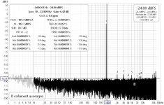 -24dBFS.jpg113.9 KB · Views: 118
 -
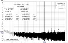 -18dBFS.jpg113.4 KB · Views: 124
 -
 -12dBFS.jpg113.4 KB · Views: 109
 -
 -6dBFS.jpg114.3 KB · Views: 128
 -
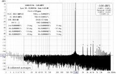 -3dBFS.jpg113.8 KB · Views: 120
 -
 -1dBFS.jpg114.1 KB · Views: 122
 -
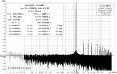 -0.20dBFS.jpg115.2 KB · Views: 127
 -
 idle.jpg261.3 KB · Views: 123
 -
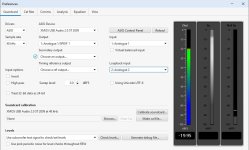 preferences.jpg88.2 KB · Views: 120
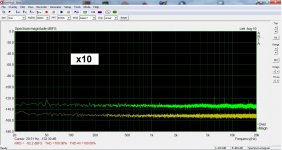
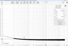
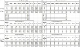
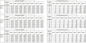
I lowered the apparent noise floor by increasing FFT length (4M) and averaging (x32) to "see" for any low level glitches (*).
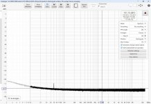
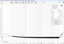
The card works cleanly at all sampling rates (attachments 1 to 6).
(*) These two settings increase the FFT execution time tremendously.
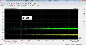
The target of a specific apparent noise floor can be achieved by a lot of combinations btn sample rate, FFT length and number of averages.
But there are no short cuts (attachments 7, 8).
For to reach the same apparent noise floor level, any such combination, takes the same FFT execution time .
Well, FFT execution time also depends on the configuration and strengths of the PC. My PC is nothing special.
The card works cleanly at all sampling rates (attachments 1 to 6).
(*) These two settings increase the FFT execution time tremendously.
The target of a specific apparent noise floor can be achieved by a lot of combinations btn sample rate, FFT length and number of averages.
But there are no short cuts (attachments 7, 8).
For to reach the same apparent noise floor level, any such combination, takes the same FFT execution time .
Well, FFT execution time also depends on the configuration and strengths of the PC. My PC is nothing special.
Attachments
-
 (1) 44k1_FFT4M_avg32 .jpg246.4 KB · Views: 154
 -
 (2) 48k_FFT4M_avg32 .jpg246.5 KB · Views: 117
 -
 (3) 88k2_FFT4M_avg32.jpg246.4 KB · Views: 113
 -
 (4) 96k_FFT4M_avg32 .jpg289.1 KB · Views: 108
 -
 (5) 176k4_FFT4M_avg32.jpg247.7 KB · Views: 111
 -
 (6) 192k_FFT4M_avg32.jpg247.7 KB · Views: 113
 -
 (7) 44.1k & multiples.jpg256.9 KB · Views: 118
 -
 (8) 48k & multiples.jpg235.7 KB · Views: 127
Last edited:
I think that Magic Bus should be proud for his creation.

George
George

Hi George,
Thank you very much for taking the time to investigate my soundcard so extensively. 👍 Such a review coming from a knowledgeable man like you makes me feel honored.
Kostas
Thank you very much for taking the time to investigate my soundcard so extensively. 👍 Such a review coming from a knowledgeable man like you makes me feel honored.
Kostas
- Home
- Design & Build
- Equipment & Tools
- DIY soundcard intended for measuring amplifiers