
Hi Ra7,I am not finding the chassis mount jack for the Mean Well SMPS input. Any help is appreciated. It is an R7B DC 4-pin connector, but there don't seem to be options in Mouser or elsewhere for the inlet jack. Thanks!
Amazon has them.
https://www.amazon.com/jing-Female-...fix=4+pin+din+con,electronics,131&sr=1-7&th=1
Ra7,
Here is the Kycon part from Mouser:
https://www.mouser.com/ProductDetail/Kycon/KPJX-PM-4S?qs=zorda86t5M/dp%2BTtr6by2g==
Here is the Kycon part from Mouser:
https://www.mouser.com/ProductDetail/Kycon/KPJX-PM-4S?qs=zorda86t5M/dp%2BTtr6by2g==
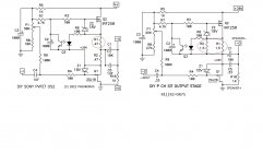
I developed the circuit equations for the DIY Sony NVFET OS2 circuit shown on page 3 of https://www.diyaudio.com/community/attachments/diy-sony-vfet-amplifier-os2-pdf.1035400/ and was able to verify that the circuit is in fact a mu-follower with the same small signal behavior as that of the Sony PVFET shown on page 4. This was not obvious when I first encountered the circuit.
It is novel in that it allows Common Drain operation with a mu follower of same polarity, in this case
N channel parts.
N channel parts.
I developed the circuit equations for the DIY Sony NVFET OS2 circuit shown on page 3 of https://www.diyaudio.com/community/attachments/diy-sony-vfet-amplifier-os2-pdf.1035400/ and was able to verify that the circuit is in fact a mu-follower with the same small signal behavior as that of the Sony PVFET shown on page 4. This was not obvious when I first encountered the circuit.
for me it was obvious from first train car, but even I had a question why Pa did it that way, instead of more logical flippin' da polarity
left that question in for later shelf, thinking mostly about turn-on thump reasons, as most likely explanation
Try my luck in this thread too, seems a bit more active than the other one. Any thoughts on using Yamaha k76 or j26 in this circuit?
Dear members,
coming from a DIY-2A3 amp. and being interested in a generation change from tubes to transistors I bought some 2SK180 VFets from ebay.
My questions:
Thanks a lot!
coming from a DIY-2A3 amp. and being interested in a generation change from tubes to transistors I bought some 2SK180 VFets from ebay.
My questions:
- Are the boards of the DIYaudiostore usable for these 2SK180 VFets - because the package of the Fets is different?
- Is the 2SK180 NPN?
Thanks a lot!
I would love to see a revision for the 2SK180. I enjoy making my own brackets. (Ok, I'm weird that way.) Currently working on a pair of L brackets for ZM's LuDEF in the new Modushop mono chassis.
ZM, since you’re only one to reply(thanks btw!).question for Pa..... he's having most experience with bigger and smaller Sonys
so, he'll know to which ones Yamaha are more comparable
would you think it’s worthwhile to just try? Even if I can get sk60/sj18?
from what I can find out, they’re single-die, but from data sheet looks to be a bit more rugged than the Sonys.
Yes plastic and Tokin version please Mr.PassOnly issue is different package. I am working up pcb art for plastic power devices that might be more cosmetic.
Alternatively I could revise the existing board for 2sk180, but I think you would have to make a bracket.

Bracket metal work for 2SK180 is relatively easy to make
and after all Greedy Boyz are FAB's 🙂
 Kind regards
From the OS2 PDF, regarding N (2SK82):As Papa said in the PDF file, set R1 at 1 Ohm, and R2 at 0 for 2SJ28 and 2SK82 vfet
"R1 + R2 determine the DC bias current and the ratio of R1 and R2 sets the AC gain. The for R1 = 1 ohm and R2 = 0, the current is constant. "
For the P (2SJ28):
"...
with R1 + R2 setting the DC current and their ratio
setting the AC, again at about 40% contribution from the current source and
fooling the 2SJ18 into thinking that the load impedance is higher. Again setting
R1 at 0 makes the current source constant, as with the 2SJ28 version."
I think he meant to say R1=1 (not 0)? In any case, when comparing the schematics side by side the original had the equivalent of R1=0.75Ω
Attachments
Must be a typo.
R1+R2, one in series and the other in parallel, set the CCS current of the respective circuits. The 2SJ28 is a higher wattage device so the current is set higher.
R1+R2, one in series and the other in parallel, set the CCS current of the respective circuits. The 2SJ28 is a higher wattage device so the current is set higher.
I bet a version that accommodates mounting board parallel to heatsink and GDS pads for flying leads (at least for SIT) would be well received (à la SissySIT).Only issue is different package. I am working up pcb art for plastic power devices that might be more cosmetic.
Alternatively I could revise the existing board for 2sk180, but I think you would have to make a bracket.
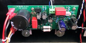
The Ship Of Theseus output stage uses two plastic power devices: a Pchannel MOSFET follower, and an Nchannel MOSFET constant current source. You can see them in the attached photo, with big fender washers pressing them onto the heatsink. Circuit is extremely similar to the Pch-VFET output stage sold in the Store by lottery last April. It is compatible and interchangeable with VFET boards, and works with all VFET front ends, VFET PSU filters, and Theseus cards.
_
_
Attachments
- Home
- Amplifiers
- Pass Labs
- DIY Sony VFETs OS2 Official thread