Or you can use a SMPS that has a 'remote control'. Such as RSP-150 series. 27V/6A for instance. or 48V/4A. Who needs more?I perceive that switches for high current DC are just difficult to source as switches for high current AC. So I'd suggest you and your circuit design squad consider the option of using a relay to switch the high current, plus a low voltage, low current switch on the front panel to activate the relay coil.

Ah, it looks like the VFET round 3 (sans VFETS) is what I'm after and I've set the notification alert for when/if they come back into stock.
I have an N channel kit I never used or opened, I bought two kits thinking (not) that two were needed for a stereo amp. Not sure how much shipping would be from USA to UK.
PM me if your interested, I will send you pics of the kit.
Thanks to the kind offer from @elwood625 it looks as though I'll be able to use my 2SK60s.
So, on that assumption, can I seek some advice on the actual project - I will target the VFET build for use with my 15ohm Lowther BLH speakers, and noting Nelson's comments about the 2SK60 having a 16ohm preference, I don't think I have to fool the 2SK60s so I'm thinking I should use R1 = 1ohm and R2 = 0ohm so that the IRF250 acts as a constant current source as per Nelson's article - am I missing something?
I will also experiment with Nelson's Full-range equalisation boards with the VFET/Lowthers.
Thanks
Last edited:

If anyone wants some more Edcor PC600-15K transformers, as used in the Sony VFET front ends {including Scourge and Bulwark}, I'm giving away a set of nine of them for free (but you pay $17 postage). And you have to un-solder them from obsolete PCBs. Here is a link to the message in the Swap Meet.
I picked up a pair of 2SJ18 from @bango in the swap meet a while back, and the P-ch OS kit from the store. Since I had built a Ship of Theseus with a linear power supply it was straightforward project to swap output stages. A neat $200 experiment.
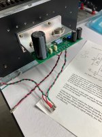
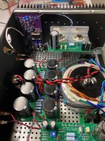
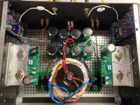
I finished building and installing the OS today with @Mark Johnson 's HORNET front end boards, one of my favorites of the three I've tried. The loaded rails read 36.6V, and with the drain of the VFETs set to 20V, a speaker load and music playing I'm getting a voltage drop of 0V63 and 0V62 across each 0R47 power resistor, so a bias of 1.32A or so. It plays some good clean music in the garage, we'll see how it sounds in the main system later on.
Happy Nearly New Years, everyone!
Attachments
Unfortunately I damaged one of my OS2 Vfet with 2SJ18. I made a modification to the brackets and had to unsolder the 2SJ18 and the IRF240 in my 6 amplifiers (4-way multiamps all with vfet except the sub). When I reassembled them I did not re-solder one of the 6 boards and, when I turned them on, the voltage rose to about 43 volts and I turned them off. I did not smell anything burning. I tried to solder the Vfet and IRF but now the voltage, once it reaches the set 20 volts, drops quickly (a couple of volts per minute). Having only a DVM, can I do something to identify the fault? Thanks to everyone for the help
considerig that biggest question is VFet functionality, best to desolder it and organize testing setup
pretty much all you need is DVM, 10K (trim)pot or two and 2 (sort of) laptop bricks, anything 19-24Vdc, so you can make 2 independent supplies connected bipolar-y
pretty much all you need is DVM, 10K (trim)pot or two and 2 (sort of) laptop bricks, anything 19-24Vdc, so you can make 2 independent supplies connected bipolar-y
- Home
- Amplifiers
- Pass Labs
- DIY Sony VFETs OS2 Official thread