
I'm thinking I might want to run a switch to the front panel, I don't care much for groping around the rear for switches, plus I think it would look cool with a lighted ring switch on the front using the LED hole as a pilot for drilling.
Plate thickness and available switches, will play a large part. Also, I would need to run the power to the front plate, or come up with another way to do the same thing.
I thought before I get down the rabbit hole, I would ask you'll what you think of the idea and pitfalls and or things to consider.
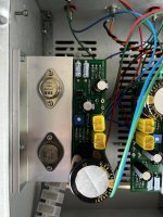
EDIT: I'm using the VFET case from the store, and I'm using the TUBA filter as well. This is the N channel version
JT
Plate thickness and available switches, will play a large part. Also, I would need to run the power to the front plate, or come up with another way to do the same thing.
I thought before I get down the rabbit hole, I would ask you'll what you think of the idea and pitfalls and or things to consider.
EDIT: I'm using the VFET case from the store, and I'm using the TUBA filter as well. This is the N channel version
JT
Same here. So I designed a PCB and started a thread about it. Click on my name in the quote below, it's a link to post #1 of that thread. When you get there you may also want to look at the photos in post #16.
I got fed up with DIY power amps whose AC mains On-Off switch is on the rear panel. This choice does reduce the amount of metal working required; just buy an all-in-one plastic molded unit containing IEC inlet jack, fuse holder, and AC mains rated switch. Cut one rectangular hole in the rear panel (where small mistakes in drilling or filing are not visible!), drop in the unit, done! But reaching through the equipment rack to operate a switch on the back panel is clumsy to watch, and awkward to do. I wanted something a little more refined ...
I read the link, but this amp will be using the 36VDC supply from the store... since this isn't dealing with mains, barring a catastrophic failure, what are your thoughts?
I perceive that switches for high current DC are just difficult to source as switches for high current AC. So I'd suggest you and your circuit design squad consider the option of using a relay to switch the high current, plus a low voltage, low current switch on the front panel to activate the relay coil.
Can I measure the body of the vfet to ground ?For P channel VFET, assuming you have a 36V power supply, you want to adjust the pot so that the Voltage at VFET drain referenced to ground is 20V.
Mark,
Yes, there still needs to be some thought as the current and voltage are both an issue for these types of switches. The rating of the PS is 4,4A and thats well over what these can handle.
Yes, there still needs to be some thought as the current and voltage are both an issue for these types of switches. The rating of the PS is 4,4A and thats well over what these can handle.
Can I measure the body of the vfet to ground ?
Yes, the body of VFETs is the drain.
For P channel VFET, assuming you have a 36V power supply, you want to adjust the pot so that the Voltage at VFET drain referenced to ground
Will the 2sk82 voltage be at 14 volts instead of 16 volts for 2sk60.? Just want to make sure , I have 2sj18 in my amp now and going to swap to p channel kit with 2sk82.Here are the changes for 2SK60 OS2 to 2SK82 Part 2. You may also need to change R5. Nelson mentioned it in his Part 2 article.View attachment 1150292View attachment 1150293
The circuit for the 2SK82 is a bit different from the 2SK60 circuit. If you build with the 2SK82 follow the 2SK82 schematic and its instructions. If you build with the 2SK60 follow the 2SK60 schematic and its instructions.
If you have the 2SJ18 right now, that is already a P channel kit. The 2SK82 is N channel and would require a N channel board.
If you have the 2SJ18 right now, that is already a P channel kit. The 2SK82 is N channel and would require a N channel board.
Thanks Ben, I bought the OS2 n channel kit to use with a pair of 2sk82 I have. I will need the 1.5 ohm R1 and R2 along with the 125 ohm (which I am having trouble sourcing) for the OS2 N channel kit. I will swap the p channels I have in the amp now.
Sorting through various spare parts I found my pair of Sony 2SK60 (JA33) devices that had hidden themselves away - it seems like a good idea to build this project so I can remember where they are in future.
Are there any PCBs or gerber files available for an N channel project - the DIY Audio store is out of stock - or do I need to set out my own using Nelson's article as the reference?
Are there any PCBs or gerber files available for an N channel project - the DIY Audio store is out of stock - or do I need to set out my own using Nelson's article as the reference?
Ah, it looks like the VFET round 3 (sans VFETS) is what I'm after and I've set the notification alert for when/if they come back into stock.
Last edited:
Ship of Theseus Gerbers won't work, they require a Pchannel MOSFET in plastic TO-3P package. Not an Nchannel JFET in a steel TO-3.
- Home
- Amplifiers
- Pass Labs
- DIY Sony VFETs OS2 Official thread