
I won't get to it for some time, I have a couple things ahead of it... That's both good and bad. 🙂 🙁
When I first read $100 I was thinking (board/s for $100) it might be a little stiff, but this is not the case with what's in the box. This price is solid, go ahead and get them if you have the VFETs it's worth every penny. This is really a great deal, for what you get.
I paid for mine, so this is not a Quid Pro Quo
JT
I paid for mine, so this is not a Quid Pro Quo
JT
Attachments
Last edited:
I get it, it was unclear to me as well, but has since been changed. I'm sure Jason would be happy to take it back, or you can sell it here when the greedy boyz miss out and have to wait for the pre-order option. 😛 I'd really like to have the P too, but I have spent major cash on Betas and other goodies. I have at least 10 amps/pres in the queue. :O

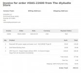
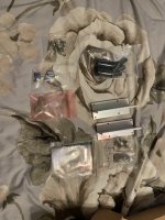
Got my p channel kit today, WooHoo! Thanks again Mr Pass & diy audio
Any thoughts on how to mount R1 & R2 to make them easy to swap out? Still kicking around the vfet chassis preorder, I'll probably try some 3U x 250MM sinks I have laying around first but two weeks is not a lot of time.
Any thoughts on how to mount R1 & R2 to make them easy to swap out? Still kicking around the vfet chassis preorder, I'll probably try some 3U x 250MM sinks I have laying around first but two weeks is not a lot of time.

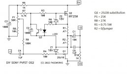
I am trying to understand why the N channel variation, using the 2SK60, doesn't use a mu follower like in the P channel variation, with the 2SK60 drain at ground, which would avoid the need for extra power supply filtering. Was there no suitable PFET counterpart to the IRF250, or was there another reason not to use a mu-follower?Attached is the document detailing the DIY Sony VFET OS2 output stages.
...
The biggest differences are in the current sources. Where the originals used constant current sources, for the P channel design we have a mu follower and for the N channel a novel variation. Both of these are constant current for DC, but can be adjusted to supply a percentage of the output current in support of the smaller VFET chips.
...

Does the switching supply care which polarity is connected to ground?I think it is to keep the use of a V+ switching power supply.
I am not familiar with switching supplies. Perhaps not all SMPS are floating, with some having the negative connected to ground.
Do you have a clever name for it? Something like 'Reverse MUFF' or 'NEMU' is what I'm hoping for...And it showcases another topology...
😀
My working name for it is not suitable for public forums.
When R2 is zero, is is a current source, otherwise it is a common-gate amplifier stage. Perhaps there a similar circuit in the tube world with a triode cathode follower (replacing the 2SK60) and another tube (pentode perhaps) replacing the IRF250. Find the name of that circuit.Do you have a clever name for it? Something like 'Reverse MUFF' or 'NEMU' is what I'm hoping for...
😀
I am not finding the chassis mount jack for the Mean Well SMPS input. Any help is appreciated. It is an R7B DC 4-pin connector, but there don't seem to be options in Mouser or elsewhere for the inlet jack. Thanks!
- Home
- Amplifiers
- Pass Labs
- DIY Sony VFETs OS2 Official thread