As far as I know only the switch mode Sony TA-N88.Does anyone know what Sony amps had these parts, 2SK82 and 2SJ28?
Yes, but you don't want significant current through the coils if you are looking for low distortion.A second question:
Can an Autoformer accept a DC voltage at the input?


signal xformers, whichever way the are wired (so, both xformer and autoformer modes) , are usually not made to have any significant DC between ends of windingA second question:
Can an Autoformer accept a DC voltage at the input?
so, shortly - both winding ends must be on same potential
now - that being on GND level or on 1KV level, irrelevant, as long both ends are on equal
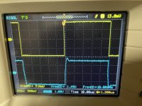
to use the amplifier without a front end, how many volts must the preamp deliver (which in my case has an output impedance of 100ohm)?
41 volts peak-to-trough.to use the amplifier without a front end, how many volts must the preamp deliver (which in my case has an output impedance of 100ohm)?
To convert to RMS, divide by sqrt(8). That gives: 14.5 volts RMS.
On the other hand, if you use the amplifier with a front end whose voltage gain is 5.0 volts per volt, you only need to apply (41/5) = 8.2 volts peak-to-trough to that front end. Or if you prefer, (8.2 / sqrt(8)) = 2.9 volts RMS applied to the front end.
You can see why Nelson Pass used a 1-to-5 step up transformer in his front end card; the transformer is able to create a 41 volt signal swing even though the front end receives only a 36 volt power supply.
Many thanks Mark for the explanation.41 volts peak-to-trough.
To convert to RMS, divide by sqrt(8). That gives: 14.5 volts RMS.
On the other hand, if you use the amplifier with a front end whose voltage gain is 5.0 volts per volt, you only need to apply (41/5) = 8.2 volts peak-to-trough to that front end. Or if you prefer, (8.2 / sqrt(8)) = 2.9 volts RMS applied to the front end.
You can see why Nelson Pass used a 1-to-5 step up transformer in his front end card; the transformer is able to create a 41 volt signal swing even though the front end receives only a 36 volt power supply.
May I ask you what would have changed if Nelson's front end hadn't had the jfet buffer driving the Edcor transformer? Impedance problems towards the preamp and towards the final stage?
Many thanks, Nelson.
When the amplifier is used in a high way active multi amp (one from 700Hz and one from 4000Hz) is there any value (capacitors and resistors) that could be changed?
When the amplifier is used in a high way active multi amp (one from 700Hz and one from 4000Hz) is there any value (capacitors and resistors) that could be changed?
My p-version is now playing, using the buffer of tombo56 and this combination sounds very good. For me the music is even more lively and direct than with the aca in the luxury part version. I am using the large Vulcan backloaded horn from Woden design. Now back to listening😎

I assume the 36V V+ applies to the Bulwark input card as well as the VFET output stage (I know, I'm a dunce but I don't want to put on my wading boots to find it).
I'm looking over my chassis (gutted TA 4650). Does the MOSFET produce as much heat as the VFET, or does the VFET produce the bulk of the heat from class A operation, or do they produce the same heat? Can the MOSFET be minimally heat sinked compared to the VFET? Expect a lot of strange questions, my first amp build.
MOSFET produces a similar amount of heat as the VFET. In my opinion (have a TA 4650 myself), the heatsink in the TA 4650 is not sufficient to operate a SONY DIY VFET. Compare the DIY VFET chassis with its two heatsinks (2x 4U300) with the TA4650 heatsinks …
Best regards, Claas
Best regards, Claas
I will be using a heat gun to determine temperature with one channel attached to the heat sink, then two channels, and then add another heat sink if required. I am doing testing as I go along, so I will test the proposition. I know that you can never be too rich, too thin, or have too much heatsink. Yes, I tend to be contrarian until I can demonstrate proof myself. I can blow up a few things since I have extra VFETs.
I suppose my question might be framed: is the aluminum bracket with the kit sufficient to heat sink the MOSFET if the VFET is remotely heat sinked. They are usually mounted together and heat each other up, but is that heat mostly from the VFET, or from both equally, or is the MOSFET operating cooler by itself.
I suppose my question might be framed: is the aluminum bracket with the kit sufficient to heat sink the MOSFET if the VFET is remotely heat sinked. They are usually mounted together and heat each other up, but is that heat mostly from the VFET, or from both equally, or is the MOSFET operating cooler by itself.
- Home
- Amplifiers
- Pass Labs
- DIY Sony VFETs OS2 Official thread