somebody should calculate dissipation of each power resistor here, then take a look at graphs in datasheets what T can be expected
only then one can be sure is there a problem, or not
only then one can be sure is there a problem, or not
I have an older version of this Flir smart phone module. It’s been a very handy troubleshooting tool.
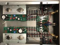
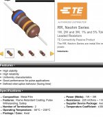
ZM: I’ll measure the voltage across the resistors later today, but I’m not too worried. I didn’t see part numbers for the power resistors in BOM but scrolling through digikey I found these which look like them. Based on the curves in the data sheet they’re probably running between half and a third of their rating.
ZM: I’ll measure the voltage across the resistors later today, but I’m not too worried. I didn’t see part numbers for the power resistors in BOM but scrolling through digikey I found these which look like them. Based on the curves in the data sheet they’re probably running between half and a third of their rating.
Attachments
Monk55,
Congratulations on completing your build!
What speakers are you planning to pair with these once the initial testing has been done?
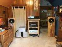
Zu audio “ Omen dirty weekend”….very good sound so far..bottom end is tight, mids are solid…highs are crisp but not bright. Overall sound is very pleasing to my old ears. I listened to my mono AJ’s prior to the NNP amp & besides the power difference they are very close @ 1W. I think #178 is a keeper. But only 8 hours so far so a ways to go but I already notice opening of sound. Currently using dual supply W2018 pre…
Attachments
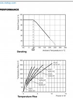
Those resistors look like the TE connectivity RR series from digikey.They have lots in stock and are 61 cents (canadian) each.Their full power max. temp. is about 75 celsius,50% power temp. is close to 155 celsius.I don't think there is much to worry about.The watts dissipated by one resistor is 0.8x0.8x1.5=0.96 watts.
somebody should calculate dissipation of each power resistor here, then take a look at graphs in datasheets what T can be expected
only then one can be sure is there a problem, or not
I have an older version of this Flir smart phone module. It’s been a very handy troubleshooting tool.
ZM: I’ll measure the voltage across the resistors later today, but I’m not too worried. I didn’t see part numbers for the power resistors in BOM but scrolling through digikey I found these which look like them. Based on the curves in the data sheet they’re probably running between half and a third of their rating.
ok, here is "somebody"

channel part:
according to https://www.diyaudio.com/forums/att...82-diy-sony-vfet-pt-1-a-diy-sony-vfet-pt2-pdf , Pa sez on first page that Iq is 1A6
means 0A8 through each 1R5 resistor (R1 and R2), and Papa's usual thingies are Pana 3W MOX
per P=I^2 * R, dissipation of each is 0W96
safety factor being above 3x, I don't care for datasheets and for fancy temperature Gizmos
you're good
PSU part:
1A6 juicing through cell of 3pcs of 3R3 in parallel, so each 3R3 battling with 1A6/3, means each is dissipating 0W94
article sez each is 5W jobbie, so bigger body so lesser temp than 3W jobbies are having on amp pcb
hasta la vista baby, just chill
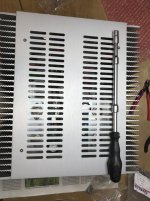
How to reach those pesky front plate screws.
Attachments
Last edited:
Jeff, an audio buddy is getting an nChannel so we can try this experiment. I didn’t mention it earlier as i figured 2 aps in such close procimity was unlikely.
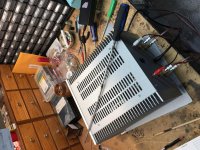
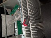
Well, I've discovered my heat sinks are a bit warped, so it looks like there's a bit of work ahead for me. I guess this is to be expected.
jeff
That said, a couple of degrees difference on the transistor bar is not big deal, and
some thermal grease will cover a lot of sins.
some thermal grease will cover a lot of sins.
Didn’t mean to cause alarm about the resistors, I was actually trying to reassure those worried about the transistor and heat sink temps by sharing some measured data.
The resistors I referred to in my earlier post were my best guess for the PS filter, not the OP board, I should really read my own posts more carefully! 🙂
Oreo382: those look like the output board resistors, thanks for sharing. I believe the 75° is for the ambient temp, operating temps look to be ~235°C
Attachments
I forgot to say the amp sounds wonderful, and it was a joy to build. Thank you so much Nelson, Jason, Elena and everybody involved behind the scenes!
How to reach those pesky front plate screws.
Similar, but less work in making the special tool ... 🙂
Regards, Claas
Attachments
How to reach those pesky front plate screws.
Awesome fabrication effort!
I was lucky several years ago and found an extra long Snap-in screwdriver that is the right length.
Sure ... but you still need to counter the nuts somehow ... 😛
much easier to get nuts on bolts than screws in holes
then , zillion different wrenches , piece of cake
been there - eons ago, after half of hour spent to put last screw in hole, without success ....... gone nutz and dismantled previous 3 ........ mounted headless screws ( whatever name is) and did it in 5 min
after that... there is just one way to do it, for me
probably as all of you , I'm mounting front plate as last ...... in fact - as I'm always using base plate, mounting front plate is much easier, because bottom and top are actually last to fit
Zu audio “ Omen dirty weekend”….very good sound so far..bottom end is tight, mids are solid…highs are crisp but not bright. Overall sound is very pleasing to my old ears. I listened to my mono AJ’s prior to the NNP amp & besides the power difference they are very close @ 1W. I think #178 is a keeper. But only 8 hours so far so a ways to go but I already notice opening of sound. Currently using dual supply W2018 pre…
That's some cool audio gear Monk55. The high efficiency Zu speakers should be a good match with DIY Sony VFET amp.
BTW, those Aleph J mono-blocks look very well built too.
- Home
- Amplifiers
- Pass Labs
- DIY Sony VFET pt 2 (N-Channel Build)