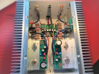
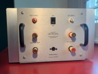
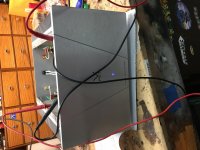
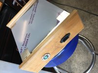
Completed the Sony Vfet Amplifier (chassis 96 of 200). It took me about 16 hours to complete the built including adjustment and lapping the heatsinks for a better fit. All electronics are the stocked items with the exception of the interconnecting and audio signal cables and wires. I also added the black handles at the back for cable and connection protection when pushing the amplifier toward the wall. I also built a simple LED light mounting bracket made from heavy plastic. The only thing left is to install some nice aluminum foots.
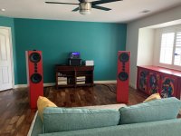
No issuers after powering up. Bias voltage was around 12.5 volts per channel. It was adjusted to 14.0 volts after about 40 minutes of warm up time. I connected it to my Tekton Pendragon speakers (rated at 95 db 1W/1M), and the amplifier had no issues driving the speaker at my normal listening level. I’m not good at describing sound but the best analogy that I can said compare to my beloved F5 Turbo, is that the F5 is like drinking whiskey and the Vfet is like drinking wine. They sound very different (at least with my setup and at my music room). The F5 is punchier and faster but the Vfet is smooth and has a very wide sound stage and has a sweet sound to it. It also can handle the bass very well. I enjoy the sound of both of these amplifier with the Tekton Pendragon.
Thanks to Nelson Pass and everyone involved including the DIY community for all the support.
Attachments

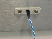
DPST from D-K
That's the DPST I also chose and just received. It seems to be a good fit.
Here is last nights Digikey shopping list:
(Mfr P/N) GRSV-4021-0006
CWI494-ND
SWITCH ROCKER DPST 16A 125V
...
That's the DPST I also chose and just received. It seems to be a good fit.
Good to see more of these N-type VFET amps being built! This one definitely has a break-in period. Give it 100 hours and it will open up noticeably, with a little more punch as well.
#178 is singing. After 50 minutes right Vfet hat 186F…irf250 hat 160F. Left Vfet hat 170F…irf250 hat 167F. Left heatsink (outside) mid OS plate 108F….right heatsink, same place, 109F. Biased right up from initial start 13.3vdc to 14vdc. Very touchy on the bias pot…don’t take much!
My “brick” measured 36.32vdc…OS measured 33.97vdc.
Now upstairs for break-in…It’s playing on garage test speakers…dead quiet.
I’m a lucky guy…Thanks to all involved & especially Mr. Pass for his overwhelming generosity!!
My “brick” measured 36.32vdc…OS measured 33.97vdc.
Now upstairs for break-in…It’s playing on garage test speakers…dead quiet.
I’m a lucky guy…Thanks to all involved & especially Mr. Pass for his overwhelming generosity!!
Attachments

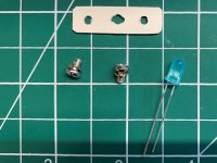
Also how are people securing the LED? There are tapped holes on either side but no hardware.
Same question. I see pics of what appears to be a diamond shaped molded plastic holder. Someone must have a part number for this.😕
jeff
Just a few dabs of hot-melt glue. Chassis hasn't gotten hot enough so far for the glue to re-melt 😀
I find the solution with strip of plastic much more elegant, though.
Regards, Claas
I find the solution with strip of plastic much more elegant, though.
Regards, Claas
Same question. I see pics of what appears to be a diamond shaped molded plastic holder. Someone must have a part number for this.😕
jeff
I just built that holding bracket with a piece of scrap of plastic thick plastic that I had.
I just built that holding bracket with a piece of scrap of plastic thick plastic that I had.
Thanks. I had the same thing in mind, just wanted to check-in first before I start digging thru the goody box.🙂
jeff
1hour…ambient temperature is 72…@F
Approximately 42°C, perfect!!
Must have been the lapping 😀
What's the optimal/desired temperature for the VFET and MOSFET? 50°C? Or is it the cooler the better?
I know heatsinks should be about 50°C, but that's just for us human convenience.
I know heatsinks should be about 50°C, but that's just for us human convenience.
I’ve not been paying much attention to this thread, Jason emailed me and my not part of the contest, round 2.5 (thanx Jason/Nelson) should be ready to ship. Chassis has been sitting for some time.
Anyway, one of things i speculated about early was what would happen if you used 2 in bridged mode like an ACA. First, i assume it is OK, is it?
Jeff, an audio buddy is getting an nChannel so we can try this experiment. I didn’t mention it earlier as i figured 2 aps in such close procimity was unlikely.
dave
#178 is singing. After 50 minutes right Vfet hat 186F…irf250 hat 160F. Left Vfet hat 170F…irf250 hat 167F. Left heatsink (outside) mid OS plate 108F….right heatsink, same place, 109F. Biased right up from initial start 13.3vdc to 14vdc. Very touchy on the bias pot…don’t take much!
My “brick” measured 36.32vdc…OS measured 33.97vdc.
Now upstairs for break-in…It’s playing on garage test speakers…dead quiet.
I’m a lucky guy…Thanks to all involved & especially Mr. Pass for his overwhelming generosity!!
Monk55,
Congratulations on completing your build!
What speakers are you planning to pair with these once the initial testing has been done?
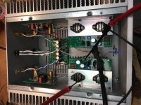
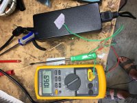
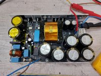
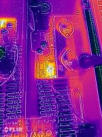
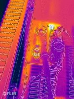
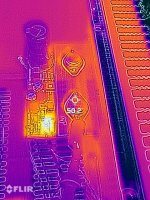
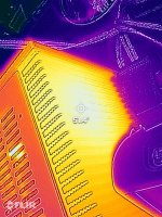
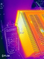
I just finished building #180 and powered it up for the first time today. I smelled something getting hot so took out my thermal imager and found out it was the big resistors on the output board (~124°C) and not the precious VFETs. The resistors on the power filter board were around 80°C, the ambient temperature in my garage was at 25°C.
I sanded my t-rails that the vfets are mounted to because I noticed they were a bit cupped, I didn’t sand my heatsinks like others did. I see about 50-52°C on the heatsinks and the cases of the output devices (after about an hour of warm up time) with the lid on, I removed for the thermal images.
Olen
Attachments
-
 C16DA73A-7733-4DF2-8D21-947C6398FC07.jpeg700.1 KB · Views: 305
 -
 9D7DA13F-033E-491B-AEFB-2359A600DC14.jpeg680.8 KB · Views: 278
 -
 E9A86519-E23D-487B-98DB-59360D92DE45.jpeg674.6 KB · Views: 272
 -
 133148E2-9E64-43FD-AB69-1F487FD563C6.jpeg639.4 KB · Views: 125
 -
 1A95DB65-D35A-4F5A-A82E-11D586D4C6B4.jpeg612.5 KB · Views: 128
 -
 643413FE-D28D-4898-A419-310A866037F0.jpeg576.3 KB · Views: 139
I just finished building #180 and powered it up for the first time today. I smelled something getting hot so took out my thermal imager and found out it was the big resistors on the output board (~124°C) and not the precious VFETs. The resistors on the power filter board were around 80°C, the ambient temperature in my garage was at 25°C.
Thermal imaging equipment? Well, I always wondered what FBI agents did on their days off.
I just finished building #180 and powered it up for the first time today. I smelled something getting hot so took out my thermal imager and found out it was the big resistors on the output board (~124°C) and not the precious VFETs. The resistors on the power filter board were around 80°C, the ambient temperature in my garage was at 25°C.
I sanded my t-rails that the vfets are mounted to because I noticed they were a bit cupped, I didn’t sand my heatsinks like others did. I see about 50-52°C on the heatsinks and the cases of the output devices (after about an hour of warm up time) with the lid on, I removed for the thermal images.
Olen
can you show the picture of the thermal imager ? Can you try a small fan inside to see how much the Temperature comes down ?
- Home
- Amplifiers
- Pass Labs
- DIY Sony VFET pt 2 (N-Channel Build)