The amplifier is probably working as it should but maybe the operator is not?🙂
The VFET case should measure hotter than the heat sink fins. Mix-up in reporting the temperatures?
The VFET case should measure hotter than the heat sink fins. Mix-up in reporting the temperatures?
🙂
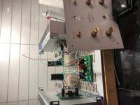
I double checked, the top of the case is is indeed around 41C. The "valley" of the fins, where the T-Bracket mounts are at 48.5C.
I'm using a Raytech Laser thermometer
And I agree, counter intuitive for sure.
I double checked, the top of the case is is indeed around 41C. The "valley" of the fins, where the T-Bracket mounts are at 48.5C.
I'm using a Raytech Laser thermometer
And I agree, counter intuitive for sure.
He did write cooling fins, i.e. heatsink fins. I interpret that as the fins outside of the amp, and they can very well be 48 degrees C. If that measurement is as interesting as a on the V-Fets is another matter.
If you measure 1 cm next to the V-FET what do you get?
If you measure 1 cm next to the V-FET what do you get?
Last edited:
Infrared thermometers may be inaccurate when measuring reflective surfaces such as bare aluminum or steel.
On the T Bracket, between the two transistors, 1cm from the transistor, i'm getting 41.5C
I see you are in Oslo, I grew up south of you, on Jeløy.
(It never reaches 41.5C there...)
I see you are in Oslo, I grew up south of you, on Jeløy.
(It never reaches 41.5C there...)
Anyone else having problems getting the screws into the front panel? Everything is loose as can be but the steel bracket is too short for the screw threads to engage with the chamfered hole. I can get the top screw into this side but something isn't square and there is a gap at the bottom while the top is tight.
You can try using washers to fill up the gap. Personally I prefer using a hammer to dong out the tabs a bit. The force of tightening up the nut & bolt will close up any gaps.
Of course the question could be rethoric . . .
Well, you will still have to slowly format them. That sort of forms an even layer in the electrolytes, reducing the DC-current though them.
Very pronounced in high voltage caps (say 400V) the effect should still exist in a 10.000 uF 75 v cap.First charge it through 50KΩ for a day or two. If my theory is right, initially the voltage after the resistor will be low and gradually increase. Once stable it is fit for use.
Secondly, parallel it with a cap, some say a mica (I have 2n7) others say >100nF, this to even out the inductance. Not a ceramic.they change capacitance with the change in AC.
I've found a small collection (x6 brand new wrapped in plastic) of these large cans last year:
https://i.imgur.com/bOiF5iXh.jpg
Date code: 44th week of 1973
I use a lot of salvaged parts in my DIY builds. I'm still alive 😀
change to thin mica & goop, for better sleep
Shhhhh....
 that's a known secret!! Below I got desperate so I went slicing

Apologies for the late replies, been away.
Just checked temperature of both the Sony's, and they are 41.5C on the casing
(both are the same)
The cooling fins are at 48C
Guess things are working as they should?
To be honest, I never found heatsinking an issue for this project as by the touch of hand, they were considerably cooler than the heatsinks in my other VFet amp dissipating 4 times the heat.
As papa said, use of thermal silicone grease can hide a lot of sins and transistors operate fine at 70C 😎
On the T Bracket, between the two transistors, 1cm from the transistor, i'm getting 41.5C
I see you are in Oslo, I grew up south of you, on Jeløy.
(It never reaches 41.5C there...)
That was really cool compared to my P channel V-Fet.

Can anyone please share the dimensions of the heatsink that is used in the official cabinet ?
Seems that the dimensions are not enlisted in the store.
Mine measure approx. 300 x 163 x 40mm
jeff
if you can keep fingers on them, all good
Hmm I can borrow an IR gun but a real thermocouple seems like a more accurate method. On mine after a half hour you can't touch either mosfet but upon cutting power you can touch them almost immediately. So it seems like the heatsinks are working efficiently.
- Home
- Amplifiers
- Pass Labs
- DIY Sony VFET pt 2 (N-Channel Build)