@ Rewind
Open chassis or chassis with vented holes is a source of high pitch oscillation.
Frequently Diyers after trimmers adjustements keep this B1K preamp open on air for tube glow show.
6L6 build guide explain how to take care about microphonic and Korg as well.
https://www.diyaudio.com/community/threads/b1-with-korg-triode.313612/post-5216102

Sorry, I should have said gate resistors on the j-fets. Should have checked the schematic before previous post. I had much the same problem with my horns. Tried using 2K from 1k which helped but finally went to 3K and cured the oscillation problem I was having. I am the one who suggested to Pete Millet to use gate resistors in his design, schematic. http://www.pmillett.com/Nutube_buffer.htmlYou might try larger grid stopping resistors. I had to increase mine.
When I discovered the First Watt J2 and experienced the resulting audio ecstasy it produced, I sold my remaining quad of NOS 6922. They commanded good money, but now I wish I still had them! Sigh...time to resort to ECC88
don't use force, use a bigger hammer ......


Debugging VFET Version 1 build. One OS does not seem to be working. I have boards from NP, with pre-installed diodes, and VFETs from Spencer, from way back when. Other channel works fine.
Swapped IS boards, knowing the one side does work well, and no output.
Double checked 20v at the resistor, so its getting power correctly.
Double checked Cap polarities.
Double checked Opto DIP6 channel in correctly
I'll be checking resistors tomorrow. And removing the bottom plate to inspect the underside.
Simple check for the VFET - in place?
orientation of zener diodes?
if OK, check them with diode test, at least
what is voltage across 1R5 fat resistor (any of these two, forming 0R75 group) ?
voltage at R9/C4 junction, or practicaly - any end of R9, ref. to GND

if OK, check them with diode test, at least
what is voltage across 1R5 fat resistor (any of these two, forming 0R75 group) ?
voltage at R9/C4 junction, or practicaly - any end of R9, ref. to GND
Thanks, it helped! Incredible. You have no idea how I have suffered. Every time the kids sceamed, the speakers were ringing in an ear piercing extremely high-pitched tone As high as I can barely hear it, but definitely feel it.@ Rewind
Open chassis or chassis with vented holes is a source of high pitch oscillation.
Frequently Diyers after trimmers adjustements keep this B1K preamp open on air for tube glow show.
6L6 build guide explain how to take care about microphonic and Korg as well.
https://www.diyaudio.com/community/threads/b1-with-korg-triode.313612/post-5216102
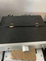
I was fresh out of lead, so I did some coin tossing, and dropped them on the floor and concluded that copper or brass has the lowest resonance tone, the thicker the better. Then I placed said coins on top of the glass of the Korg Nutube, and taped 60cm of vulcanic tape around it. Then I added some vulcanic tape cushions under the pcb boards four screw holes. For better ground I scratched up the surface around the power connector and added a toothed star lock washer. Then I taped some brass coins around the chassis, top and bottom. Ringing is almost gone.
But my comouter got heat stroke after last nights gaming session and now RF noises are leaking out, even trough optical (onboard connector on the motherbord). Time to bring out the Zero Dac AD1852 project.
Attachments
Now there is something with the B1 Triode preamp that causes RF noise from the computer to travel through the power outlet to mostly the right speaker channel. I can hear when I move the computer mouse, but that noise stops when I disconnect my monitor. But the main RF noise is still there. The noise stops when the computer is off. I removed the XFX 6900 XT graphics card and started up without image, but the noise was still there. It started in the middle of the night, i.e. before todays vulcanic tape experiments, and I thought to my horror that it was the Sony V-Fet pt.1 that crapped out. There is only optical toslink between PC and Minidsp. It must be a ground loop through the ground in the wall to my minidsp 4x10HD. I am so ready for the DIY 6-24 active crossover!
Strange thing is that my other B1 Triode does not have this problem and is dead quiet, except for the ringing, since I have not taped brass coins with vulcanic tape to that Nutube yet.
I can try to connect them identically, and flush some solder joints in search for a cold solder point, and review the forums for proper grounding of the chassis.
At least I can cancel my request for a new PSU for the Sony V-FET as they seem to both work fine and was not the cause the ringing, that I thought was coil whine from the Sony V-FET PSU.
Last edited:
orientation of zener diodes?
if OK, check them with diode test, at least
what is voltage across 1R5 fat resistor (any of these two, forming 0R75 group) ?
voltage at R9/C4 junction, or practicaly - any end of R9, ref. to GND
View attachment 1068602
Diodes aligned correctly - my Fluke 87 V says they work correctly
Voltage from PSU board - 33.7
Voltage across 1R5 - 1.22
Voltage R9/C4 to ground 24.67
(Potentiometer adjusted, as per the guide, to 20v)
well, everything seems fine
did you tried bringing input signal from second channel - either taken directly from input pads of OS or output pads of FE?
I mean, if all parts are in place, if OS is verified to have proper Iq and proper voltage level of output node, how on earth is possible that "One OS does not seem to be working." ?
Yes, I have to check the entire chain - RCA > Wire > IS > wire > OS > wire > Binding posts.
I hurriedly swapped IS cards, but need to do more careful, methodical, testing. I’m going to get the good side going, then swap that “working” input chain to the questionable OS (just wires), and visa versa. It would be good to prove both IS work, and try to work down to the malfunction.
I hurriedly swapped IS cards, but need to do more careful, methodical, testing. I’m going to get the good side going, then swap that “working” input chain to the questionable OS (just wires), and visa versa. It would be good to prove both IS work, and try to work down to the malfunction.
it seems that you have a problem upstream of OS, except in case that you made dead short between input pads on it
I decided to do the VFET project with the 2SK60's. Assembling and ordering stuff now. There is a dearth of chassis info at the store and I don't want to "miss the boat" size wise. Can somebody tell me what the inside dimensions of the "special" VFET box are? Thank you very much for your help.
Don
Don
Still pinching myself over my great good fortune lucking into literally the last of the Sony P-ch VFET kits. During the original lotto window I was deep in the Klamath river valley, driving & out of cell phone reception, on my way home from a welfare check on my estranged brother. Not that I had the clout to be viable in the lottery anyway, but the hope was there. I remember that day buying a turkey sandwich for lunch, only to find an hour down the road that they'd forgotten to put in the turkey. I had to laugh, and did. It's funny how life turns out some times.
Anyway I couldn't wait for the chassis or the brick, the soldering iron had to come out today. Here's a family portrait.
Thanks so much to Papa and to all the DIY volunteers and supporters of BAF 2022 for their selflessness and generosity.

Anyway I couldn't wait for the chassis or the brick, the soldering iron had to come out today. Here's a family portrait.
Thanks so much to Papa and to all the DIY volunteers and supporters of BAF 2022 for their selflessness and generosity.
ranshdow, I think it's a fun build and I'll second what Jim wrote: you will love it.
One thing I want to remind you is that there were some boards with a silkscreen issue on the polarity of the output cap. Please have a look at the posts starting here and see if that affects you:
https://www.diyaudio.com/community/threads/diy-sony-vfet-builders-thread.370689/page-8#post-6623731
Cheers,
Dennis
Yes, thank you Dennis. I happen to be at that point in this thread and I did a quick double check just now; C1+ on the OS boards points to the heatsink so I'm good 🙂ranshdow, I think it's a fun build and I'll second what Jim wrote: you will love it.
One thing I want to remind you is that there were some boards with a silkscreen issue on the polarity of the output cap. Please have a look at the posts starting here and see if that affects you:
https://www.diyaudio.com/community/threads/diy-sony-vfet-builders-thread.370689/page-8#post-6623731
Cheers,
Dennis
Beware of Danaians ........
when Pa sent me Papa's Koan, with boards semi-populated ( just picolo parts missing) I was thrilled to see that pinout for input buffer JFets is different to usual Toshiba TO92 jobbies; trembling, hoping that he found some alternative ones, I sent him an e-mail asking for that detail...... and he just replied - "naah, that's just an error on test run of pcbs ..... "
back to Toshibas, he pulled my leg(s) for oomphtteentht time
Oh f*... you know, I was worried about this yesterday, and I followed the silkscreen for orientation. Now looking at spec sheets, & the schematic, dammit these things are in backwards... their sources should be tied and connected with the blocking cap, not their drains. Looks like some delicate surgery is in the forecast.Beware of Danaians ........
when Pa sent me Papa's Koan, with boards semi-populated ( just picolo parts missing) I was thrilled to see that pinout for input buffer JFets is different to usual Toshiba TO92 jobbies; trembling, hoping that he found some alternative ones, I sent him an e-mail asking for that detail...... and he just replied - "naah, that's just an error on test run of pcbs ..... "
back to Toshibas, he pulled my leg(s) for oomphtteentht time
Edit: Thank you ZM. This is the second time you've saved my tail.
😕
- Home
- Amplifiers
- Pass Labs
- DIY Sony VFET pt 1