Hi Claas,
Thanks again for sharing all these feedbacks, appreciated 🙂
Few notes on these (and previous ones), just thinking out loud...
1) I am glad that these additional filters brought some benefits again, always a welcome plus I guess, especialy when starting on such an optimised unit
2) Deep bath contains indeed a lot of room informations that are quite enjoyable when it comes to sound reproduction, so better and deeper bass often bring better soundstage and realism IME, regardless the required frequency band needed by music instruments only. I also prefer closed box than bass reflex ones in that regard, but that is another discussion...
3) I am surprised that the benefits of the said filters seem not as huge as the ones we noticed in our implementation (admittely only one sample). For me it is quite a step, next comes the additional PS caps, and both these PS tweaks are miles ahead of the other tweaks I tried. Now, without diminishing the quality of the used speakers, I wonder about the following: the PS filter benefits are especialy located in the lower and in the higher audio frequency bands - no change whatsoever in the mids on my side. For me the also existing soundstage changes result probably mainly from the LF and HF improvements. I haven't tried the VFET on my main system (I don't think it can drive my quite inefficient / demanding speakers, closed box with 25Hz... to 45kHz @-3dB response) but "only" on a pair of Klipsches reaching low "only" advertised 32Hz @-3dB. Now, if one uses wideband drivers with the VFET, and again not diminishing the quality of such a system (not even knowing what was used!), but just noting that "usualy" they per definition don't shine in the LF and HF department (compromise, compromise...), I wonder if the perceived benefits of the said SMPS filters might not be in that case "less than with full range speakers".
4) Whereas I am very happy to note that the 100Hz residual has been reduced, I must say I have no clue whatsoever as why this can be, given that the additional SMPS filters shouldn't really act in these frequency ranges! Perhaps some side effect of some additional capacity (???) but then if so, adding PS caps could only help.
5) I am still amazed to see how much of that 100 or 120Hz PS noise is present, whereas we use a SMPS. That looks like quite a lot, eventhough I am well aware that I don't hear with scopes and that what the machine reveals as being quite a lot might not even be noticed by my ears, who knows... On the other hand, I wonder if trying a mains filter before the SMPS could bring further sonic benefits - something I discarted so far as A) SMPS are supposed to be quiet in that regard, B) I don't know how said SMPS works and if a conventional mains filter upstream would change anything or not - I might be better off simply trying it out rather than giving myself headache with theories LOL!
6) Yes, adding also PS caps is a great tweak. I started there, so perhaps there is more synergies between the 2 tweaks and the filters "shine" more once the PS caps have been added (and vice-versa?). Who knows? I only retained that both tweaks were easy ones with, IMHO, great results and ROI. And they belong together "somewhere"
Thanks again for sharing all this and looking forward to your feedbacks with FE cards 🙂
Claude
Last edited:
Hi TungstenAudio and ClaudeG,
sorry, this ended up in the VFET pt 1 thread - I have a VFET pt 2, the N-channel version. So my replies might be a bit confusing ... 😱
For what it's worth, I would still like to give some additional info:
- I already had an additional 1000 uF at the input of each output stage module when I did the first measurement. That tweak I did already a few weeks ago, together with a 1000 uF Nichicon UKZ paralleling the output cap C1. Maybe that's why I only felt a smaller improvement from adding Mark's filters.
- I now have as filtering inside the amp, per channel, the RC on Nelson's board (1R1 - 3000 uF), then Mark's filter board (relevant for low frequencies: RCRC with 0R050 - 470 uF - 0R050 - 470 uF), and the additional 1000 uF at the entry of the output module. I believe the small reduction in 100 Hz hum is due to the additonal RCRC of Mark's filter.
- In Nelson's article on the VFET pt 2 (N-channel), he mentions that the N-channel version is more susceptible to noise from the PSU than the P-channel version because of the low Drain impedance of the VFET. He provided more filtering in the power distribution PCB of the N-channel version. I note that in the N-channel version, he put in more of a low-frequency filter rather than the high-frequency filter of the P-channel version.
It would be interesting to see a measurement from a P-channel VFET to see if the 100 / 120 Hz hum component is lower in that version.
As to why 100 / 120 Hz is to be seen in the amp, when we have a switchmode PSU: Here I can only guess. My guess would be towards some coupling in the PSU between the primary side (probably bridge-rectified line AC, so 100/120 Hz ripple) and the high-frequency transformer that's transforming down the chopped-up primary ripple-ridden DC. With about 3.2A at 36V, we are putting already a significant load on the PSU with regard to its rating of about 4.4A, so it has to work hard.
Regards, Claas
Ah, thanks for the update Claas, explains quite a few bits indeed if not around the same VFET amp version!
Indeed yours is more sensitive to PS (perhaps that 100Hz residue would be less on my VFET version?) and yours indeed has already a much stronger SMPS filter by Papa, so adding another one (Mark's...) might not yeld as much benefit as on our First version VFET amps.
On a side note though, regarding your comments...
Quote "I now have as filtering inside the amp, per channel, the RC on Nelson's board (1R1 - 3000 uF), then Mark's filter board (relevant for low frequencies: RCRC with 0R050 - 470 uF - 0R050 - 470 uF)"
=> In fact it is IMHO rather the opposite. The original Papa filter you have, admittely "stronger" than ours, is more relevant for lower frequencies filtering. It is first order with Fc=53Hz (and presumably less effcicient at highish frequencies where the ESR of the R is a problem, whereas L components can address the HF better).
On the other hand, Mark's boards are 4th order with Fc=5kHz... More relevant for HF results, and incoportates inductors. That's on the paper re filtering, doesn't mean of course HF can't upset the amp and filtering these out... lead to better LF response to our ears (as it did).
The Papa filter we have in our units is second order (LC) with Fc= 460Hz. Half way solution, not as "deep reaching" as your Papa filter, not as specialised in HF rejection as Mark's.
That's the reason why I combined both and gave it initialy a try (long post on the thinking behind). Doing so I though realise I didn't suspect n x 100Hz garbage to be a any potential problem on our amps... and didn't try, so far, to address it.
Quote "I note that in the N-channel version, he put in more of a low-frequency filter rather than the high-frequency filter of the P-channel version.
It would be interesting to see a measurement from a P-channel VFET to see if the 100 / 120 Hz hum component is lower in that version."
=> Agreed on both!
Thanks for all this again
Claude
Last edited:
Hi Claude,
yes, I think I wasn't clear enough in my wording ... what I meant was that in Mark Johnson's filter, at low frequencies, we need to take only the DC resistance of the inductor into account, which for the one Mark suggests is 0R010. Together with the series resistance of R1 this would give 0R050 DCR for R1+L1. So I did look at the filter as RCRC at 100 Hz with 0R050 - 470 uF - 0R050 - 470 uF.
At high frequencies, when the inductor has a high impedance, this filter provides much better damping, as you mentioned 🙂.
Regards, Claas
Attachments

OK!
Meanwhile I looked into existing 2200 to 3300uf caps and a pair of 4mH coils to accomodate them (instead of the existing RC parts) on the small original filter board we have, to address potential 100/120Hz hum. That should suppress it quite a bit more than our current mid frequency filter... should it be needed (and that's the key point!)
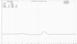
HOWEVER, I remembered that an early builder did a scope trace on our VFET amp re 120Hz noise. I tend to keep record of all this in a file, to help my poor memory. Sorry, I can't remember who posted it, I only hope he doesn't mind me posting it again (if a prob I would of course take it out) and all credits go to the original poster! IF my memory serves me well, wasn't it "you" who experimented first the sad output cap blow and helped many other members avoiding it (?)... perhaps... thanks again!
On that trace one can see that 120Hz doesn't really seem to be a problem for our first edition VFET amps. It is roughly 30dB down on what second edition owners are experimenting (if posted traces are to be believed and my understanding is correct), and that overall lowish level is even without any mod (additional caps and filters), likely to shave off a few additional dB. So... I basicaly wasted a couple of hours looking for potential parts replacements... that could solve a problem that doesn't exist! LOL, typical me!
Of course if anyone else did a measurement, glad to be proven wrong, not that I want to find an excuse to keep tweaking that little gem forever LOL
Claude
Meanwhile I looked into existing 2200 to 3300uf caps and a pair of 4mH coils to accomodate them (instead of the existing RC parts) on the small original filter board we have, to address potential 100/120Hz hum. That should suppress it quite a bit more than our current mid frequency filter... should it be needed (and that's the key point!)
HOWEVER, I remembered that an early builder did a scope trace on our VFET amp re 120Hz noise. I tend to keep record of all this in a file, to help my poor memory. Sorry, I can't remember who posted it, I only hope he doesn't mind me posting it again (if a prob I would of course take it out) and all credits go to the original poster! IF my memory serves me well, wasn't it "you" who experimented first the sad output cap blow and helped many other members avoiding it (?)... perhaps... thanks again!
On that trace one can see that 120Hz doesn't really seem to be a problem for our first edition VFET amps. It is roughly 30dB down on what second edition owners are experimenting (if posted traces are to be believed and my understanding is correct), and that overall lowish level is even without any mod (additional caps and filters), likely to shave off a few additional dB. So... I basicaly wasted a couple of hours looking for potential parts replacements... that could solve a problem that doesn't exist! LOL, typical me!
Of course if anyone else did a measurement, glad to be proven wrong, not that I want to find an excuse to keep tweaking that little gem forever LOL
Claude
Attachments
Last edited:
The amount of 100 Hz hum at the amplifier output, is simply the amount of 100 Hz hum on the DC supply rail, times the 100 Hz attenuation of the (output stage with loudspeaker load).
Since the two VFET amplifier types have very different output stages, it's no surprise that they have very different amounts 100 Hz attenuation.
Nelson Pass's pdf design brief talks about the very low drain impedance of these VFET transistors. Do you suppose it might be an important factor in hum attenuation, too?
_
Since the two VFET amplifier types have very different output stages, it's no surprise that they have very different amounts 100 Hz attenuation.
- The first batch of amps (P-VFET) have a CCS to the positive supply rail, plus a follower whose drain is connected to the negative rail, ground.
- The second batch of amps (N-VFET) have a CCS to ground (the negative rail), plus a follower whose drain is connected to the positive supply rail.
Nelson Pass's pdf design brief talks about the very low drain impedance of these VFET transistors. Do you suppose it might be an important factor in hum attenuation, too?
_
Last edited:
The Tuba filter will amputate that 100Hz spike and make it completely disappear from your FFT. Whether or not that provides any sonic benefits, I do not know.
_
_
Brought my DIY VFET back into the main system after living with my F5 and ACP+ for about a month.
This is my first experience with this combo. The VFET and the ACP+ are an excellent match. The VFET is such a lovely little amplifier. I may play around this weekend with the different kinds of speakers I have in the house (Manzanita OB, Planet10 P7HD fullrange Microtowers, Econowave woofer and compression driver 2-ways).
I'm itching terribly to build the ACAmini as soon as boards are available... 😀
I think a lot of people are excited about it. It sounds like a nice, possibly inexpensive, option to building a large f6, f5 etc. I want to get my mitts on one.
1/ Output caps: Western 4600uF x 2 + Black Gate non polar 4700uF x 1 + Rubycon Twist STLX 0.47uF x 1
2/ Input caps: Western oil 0.01uF x 1 + Black Gate NX Hi-Q 0.47uF x 1 + Rubycon Twist STLX 0.47uF x 1
3/ All BeO TO-3 insulators
4/ Duelund silver cotton oil wires for input and output interconnect
5/ Not used FE board
6/ Not used ON/OFF switch
7/ Short circuit R4
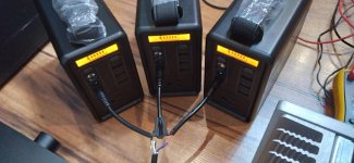
8/ Beaudens B-1502 (166Wh) LiFEPO4 battery x 3 in serie wiring (playing around 3 hours)
Have fun...
2/ Input caps: Western oil 0.01uF x 1 + Black Gate NX Hi-Q 0.47uF x 1 + Rubycon Twist STLX 0.47uF x 1
3/ All BeO TO-3 insulators
4/ Duelund silver cotton oil wires for input and output interconnect
5/ Not used FE board
6/ Not used ON/OFF switch
7/ Short circuit R4
8/ Beaudens B-1502 (166Wh) LiFEPO4 battery x 3 in serie wiring (playing around 3 hours)
Have fun...
V-FET Nr 038 has been up and running for almost 9 month now
My gratitude goes to Pa and those many who have made all this possible
In the past 50 years i have built a lot of amps, as we all do, in the quest for the holy grail
and this V-FET is a marvel like none
It has the rare property to make itself forget in favor of the music like none other i have come across
It has its limitations (modest power and damping factor), but paired with the right speaker
it is immensely rewarding
My speakers are efficient low qts 5"fullrangers ACR FP163 (derivate of Fostex) and i listen to
classical music and Jazz
Again
Many thanks and happy coming new year
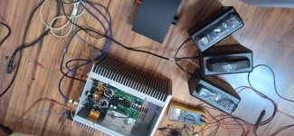
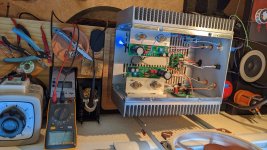
V-fet no 025 is finally playing music. After moving country, I finally got my little workspace set up.
Thanks again and happy new year to Nelson, Jason and the rest of you involved in this.
Happy new year to the jester and the greedy boyz aswell.
Now I need to sort my speakers out and do some burn in.
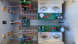
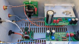
Here are some pictures of my build...
Thanks again and happy new year to Nelson, Jason and the rest of you involved in this.
Happy new year to the jester and the greedy boyz aswell.
Now I need to sort my speakers out and do some burn in.
Here are some pictures of my build...
Attachments
Could you post or link to schematics?high current SMPS filter // after the ~ 200 VFET kits are gone
Of course, nobody who is lucky enough to win the buyer's lottery and obtain one of these amps, would ever think about changing any aspect of Nelson's design. You use his circuits, his boards, his specified part-numbers, and you even wire the chassis using the same colors of insulated wire as he drew on page 11 of the pdf manual. When Picasso says "paint this Cadmium Yellow," you don't argue, you go buy Cadmium Yellow paint and you follow his instructions.
However, after those approx. 200 amp kits are sold and built and installed, the post-VFET versions will thrive and multiply. Builders with lots of chutzpah & bravery will no doubt add embellishments, accessories, and features not present in the original NP VFET design.
One such possibility, still just a prototype, is shown below. It's a four pole lowpass filter, which replaces Nelson's two pole filter shown on page 6 of the pdf manual. The goal of this PCB is to remove even greater amounts of hash, crud, noise, ick, and general HF unpleasantness from the SMPS output, providing an even cleaner DC supply to the amp. As you can see for yourself if you look up the inductor part number -- clearly visible in the stunning photographs taken by wizard 6L6 -- the components themselves are good for about 9 amperes of DC current. Each VFET channel draws less than 2 amps, and my wet-finger-in-the-breeze guess is that future non-VFET channels will draw less than 3 or 3.5 amps. So there's a nice margin of safety. When you order PCBs from fab, should you specify double-thick (2 oz) copper? Oh yes.
I'm still testing the board and performing experiments. It may not pass the tests, the experiments may fail, and this board may never get released. But, fingers crossed, so far so good.
The top side silkscreen says "6A maximum" because I've provided flexible PCB footprints that accommodate several different inductor part-numbers. Expecting the inevitable backorder / out of stock / we don't have Mouser in my country / kinds of difficulties. The highest current inductor that fits, is rated 9.8 amperes. The substitutes that fit, have lower current ratings, including one rated for "only" 6A. The top silkscreen makes the conservative worst-case assumption that the builder has been forced to purchase the scrawniest inductor.
_
TIA
Felipe
Bulwark boards - done
Dreadnaught build - pending
TUBA board - done
Hoping to build the p-channel boards this weekend (on call, and some CME to do)
- thanks again to the wonderful Mr Pass for those boards - 🙂
I’ll need to start by leveling the back side of the T heat spreaders.
Modushop looks to be shipping the chassis to some people. Maybe I get shipping notice soon.
This amp could come to life over the Memorial Day weekend, if the chassis shows up.
Last edited:
Yes I got my chassis yesterday in The Netherlands. But I still need to establisha good driver stage. I have 10* transformers (+20dB) that are designed for balanced use, have 150K bandwidth being made of Unobtanium doped with Secretum. But I am uncertain if the sound is good, because the laminations look thick.

- Home
- Amplifiers
- Pass Labs
- DIY Sony VFET pt 1