Pa wrote somewhere that Sony VFets likes 16-ish R load, and the're getting that with 8R speaker, combined with action of Mu Follower, facing VFet
when using 12R spk, that results in 24-ish load, which can be polite (lower THD) but less lively
when using 12R spk, that results in 24-ish load, which can be polite (lower THD) but less lively
If I remember correctly, the 16R - preferred load was for the "small" Sony VFETs (2SJ18 / 2SK60) - that's why they will get a Mu Follower in an upcoming variant of the DIY VFET amp.
I think the VFETs in part 1 (2SJ28) and part 2 (2SK82) like 8R loads - that's why the got a CCS.
Sorry, don't remember the post from the top of my head, will search for it ...
Edit:
Here: https://www.diyaudio.com/forums/pass-labs/370282-diy-sony-vfet-pt-1-a-37.html#post6602753
and here: https://www.diyaudio.com/forums/pass-labs/370282-diy-sony-vfet-pt-1-a-111.html#post6696445
Regards, Claas
Last edited:

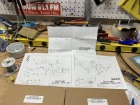
quote from pg 17
"The amplifier is particularly happy into 8 ohm speakers with efficient drivers -
I suggest 90 dB/watt or higher, although you are welcome to try any load you
like – this amplifier is not easily damaged."
"The amplifier is particularly happy into 8 ohm speakers with efficient drivers -
I suggest 90 dB/watt or higher, although you are welcome to try any load you
like – this amplifier is not easily damaged."
Agreed, But it is nice to know why.
The spectral content of the thd is dependent on the impedance of the
load, since it affects the load-line of the Vfet/SIT.
Works just like a Triode in this regard.
As a general approach we optimize it against an 8 ohm resistive load.
If you have a different load, it can be biased more toward that, or
you can give it some help, like with a mu-follower, or you can adjust
the load itself...

Scourge, Bulwark, Marauder, and Dreadnought are now available as full kits including PCB and all electronic components. Yes even the Edcor transformers.
VFET Front End cards :: diyAudio Store
VFET Front End cards :: diyAudio Store
Hi all,
now it should finally go on but I can't find my little syringe with the thermal grease.
I can me remember only the was from Halnziye. Can anyone tell me what type of Halnziye it was (hy710, 880 or something else).
Thank you very much!
now it should finally go on but I can't find my little syringe with the thermal grease.
I can me remember only the was from Halnziye. Can anyone tell me what type of Halnziye it was (hy710, 880 or something else).
Thank you very much!
I changed for Noctua grease. Leadinng brand for high power CPUS. But the chinese stuff should work good too.
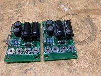
I put these little filter critters in my vfet, one per channel. Seems a bit more 3D and deep in the soundstage. I’m doing a victory lap by cranking a favorite record at proper volume for the style: Tanith - In Another Time LP. Love it. On an SP10 - thanks Jim!
Next up will be some front end boards.
Next up will be some front end boards.
Attachments
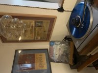
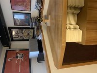
Interesting, how does the Hartfield like to be driven by a SET VFET Amp?
Horns and vfets are a perfect match!
Glad you enjoyed the additional filters in your VFET!
On top of the better soundstage, with time you may appreciate quite a step re tonalities, resolution (better highs and lower bass, helping in fact the better soundstage) and especialy music flow
And yes, perfect match for horns, I agree!
Enjoy music
Claude
On top of the better soundstage, with time you may appreciate quite a step re tonalities, resolution (better highs and lower bass, helping in fact the better soundstage) and especialy music flow
And yes, perfect match for horns, I agree!
Enjoy music
Claude
Hi Randy and everybody,
we seem to be on a parallel path here ... I also added the PO89ZB filters to my DIY VFET (N, so 2SK82), one before each output stage.
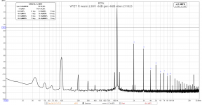
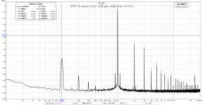
Music-wise, the main difference I noticed was a bit more transparency in the bass (more info - you can better hear what's going on with all the instruments), and a bit less sibilance in some recordings. Otherwise, I don't have a lot of difference to report. I feel that the little hum that the amp has, has gotten a bit quieter. You have to be very close to my 100 dB/W widebanders to hear it. I took some distortion measurements before and after adding the PO89ZBs, and you can see a slight reduction in the 100 Hz peak. (second picture with later date is with the filter)
I now measure 480 uV AC at the outputs (both channels the same) - unfortunately, haven't measured that before adding the filters.
I guess the about 900 uF of filter capacity the PO89ZB adds helps a bit.
Next step will be some different front-end boards as well. I have a pair of completed and dialed-in Marauder boards sitting on my bench, but want to memorize the sound with the original front-end a bit more before I swap.
I'm really curious if an Edcor-less front-end will change the measured hum (since it's 100 Hz in the first place, and then also the Meanwell PSU is far away, I guess not), but expect much better square-wave response and frequency responce. Let's see ... 🙂
Best regards, Claas
we seem to be on a parallel path here ... I also added the PO89ZB filters to my DIY VFET (N, so 2SK82), one before each output stage.
Music-wise, the main difference I noticed was a bit more transparency in the bass (more info - you can better hear what's going on with all the instruments), and a bit less sibilance in some recordings. Otherwise, I don't have a lot of difference to report. I feel that the little hum that the amp has, has gotten a bit quieter. You have to be very close to my 100 dB/W widebanders to hear it. I took some distortion measurements before and after adding the PO89ZBs, and you can see a slight reduction in the 100 Hz peak. (second picture with later date is with the filter)
I now measure 480 uV AC at the outputs (both channels the same) - unfortunately, haven't measured that before adding the filters.
I guess the about 900 uF of filter capacity the PO89ZB adds helps a bit.
Next step will be some different front-end boards as well. I have a pair of completed and dialed-in Marauder boards sitting on my bench, but want to memorize the sound with the original front-end a bit more before I swap.
I'm really curious if an Edcor-less front-end will change the measured hum (since it's 100 Hz in the first place, and then also the Meanwell PSU is far away, I guess not), but expect much better square-wave response and frequency responce. Let's see ... 🙂
Best regards, Claas
Attachments
Last edited:
It may be interesting to try adding a modest amount of extra capacitance to the power rail on each output stage. The filter board may work to prevent the SMPS from going into a hiccup current limiting mode. Try values from 1000 uF to 10,000 uF.
Judging by the differences you have already mentioned, you can expect better bass instrument articulation, and improved separation.
Judging by the differences you have already mentioned, you can expect better bass instrument articulation, and improved separation.
By the way, I think you will be in for a treat when you swap in your Marauder front-end boards. I am currently enjoying mine in the system.
- Home
- Amplifiers
- Pass Labs
- DIY Sony VFET pt 1