This is the cap at the input of the Edcor signal transformer. 220 uF is still more than enough.
Ahhhh gotcha. Out of curiosity, does that cap influence at all the high frequency response (similar to altering the leakage inductance or capacitance of xformer itself)? Curious what you observed with that mod.
Sorry to pester, I'm just trying to act like a sponge and learn more along the way. 🙂
If you want an eye opener, try building a pair of Bulwark front end boards for your VFET amp. They have a pair of coupling caps between the amplifier circuit and the transformer. So you can try all sorts of combinations. (I found that a pair of Elna Silmic 100 uF caps sounded very good.) You can also leave the amp circuit as unity gain or increase the gain a little by adding three components.

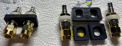

lovely binding posts but they will not fit .... but now! The new ones looks nicer. 😀
I had some of those come by in a set of Victor. I thot they sucked.
dave
What you mean with a „set of Victor“?I had some of those come by in a set of Victor.
OkI thot they sucked.
Nice pictures but i didn‘t know what you mean. Ok, this diskussion is not part of this thread.
The binding posts were brought by the client to install in the Victor he had built. They were disappointing and replaced with something better (IMM) and cheaper.
dave
dave
While forcing R8 (27K) to behave using a needle nose I chipped the (ceramic ?) coating. Should I replace it?
h Mr. Pass ,
what is the new updated manual or instruction for Sony vfet ?
thanks
what is the new updated manual or instruction for Sony vfet ?
thanks
Now is the winter of our discontent made glorious summer by sunny skies
and celebration of my 20 years on this forum, not to mention recent
vaccinations...
I present the DIY Sony VFET pt 1, detailing the design for the P channel
amplifier version using up the last of the Sony 2SJ28 VFETs, to be followed
by part 2, using up the 2SK82's.
diyAudio will be offering a limited quantity of complete kits of both versions,
so watch for the announcement in the store.
Later there will also be offerings for those who have these and the other
Sony VFETs already, and also other FET devices.
Further reading and discussion:
I can comfirm this amp definitely works better with an 8Ω load. I ordered some Zu Omen Dirty Weekends (I always wanted to try Zu's) which is 12Ω. It was okay, but not really impressive. Its supposed to be 97db efficient but the volume was noticably lower than my 94db Audio Nirvana 15" alnicos. Paralled some 50Ω and they improved greatly. 39Ω even more. Much more dynamic. Speakers really sing now. A contender to replace the AN
in any case - if shunting speaker results in better sound, point isn't in number representing impedance of speaker (who cares?) but it is showing amp's preference for lower load
which we know is pretty normal with triodes - you can try different OPT taps and choose which one suits you better with your speakers 🙂
though, these puny sand triodes are not having OPT mounted, so other ways must be used to help

which we know is pretty normal with triodes - you can try different OPT taps and choose which one suits you better with your speakers 🙂
though, these puny sand triodes are not having OPT mounted, so other ways must be used to help
Thanks for pointing to these LS, unknown to me, interesting.
Impedance curve can be donwloaded on their site.
Varies from 8 to 50R.
Claude
Impedance curve can be donwloaded on their site.
Varies from 8 to 50R.
Claude
in any case - if shunting speaker results in better sound, point isn't in number representing impedance of speaker (who cares?) but it is showing amp's preference for lower load
Agreed, But it is nice to know why.
A parallel R will both lower & flatten the impedance. You are doing 2 things at once.
Is the flatter curve? We know high Rout amplifiers like a flattish impedance. I haven’t seen a measured impedance of the dirty WE but every other Zu measured curve i have seen is ugly.
dave
Manual has the curve.
Resonance peaks of 50 and 40 Hz, otherwize varirs from 8Ω to 20Ω, paralleled with 39Ω it varies from 6.6 to 13.2Ω. Resonance peaks 19 & 21Ω.
dave
Resonance peaks of 50 and 40 Hz, otherwize varirs from 8Ω to 20Ω, paralleled with 39Ω it varies from 6.6 to 13.2Ω. Resonance peaks 19 & 21Ω.
dave
- Home
- Amplifiers
- Pass Labs
- DIY Sony VFET pt 1