Pass DIY Addict
Joined 2000
Paid Member
Zen: I thought about this as well, particularly the transistor interface since the creak happens so close in time to the power on/off cycle. In my case, this interface is mica & goop. I haven't gone back to check the TO-3 mounting screws in a little while, though. Might be worth checking on...
due to these mishaps, I even got so hysteric that I bought torque screwdriver ")
magic number, by Pa -
that's ~ 0.9Nm
magic number, by Pa -
I recommend a nice wide washer on top.
The TO247 case has good support at the hole, and you
just want to avoid cranking down too hard. We use
torque wrenches set at 8 inch-pounds.
that's ~ 0.9Nm
Pass DIY Addict
Joined 2000
Paid Member
how does the logistics of this work out? Once this design has been finalized, its sent to your PCB fabricator, and they just crank them out to the tune of about a week or so, and send back your way?
Is this the same supplier of boards that you use for other projects as well?
In the old days, we would tape up a design and send it out to be
photographed and then place an order with the pc house. A proto board
would cost about $1,000 (old dollars) and take about a month.
Now with computers and internet and Chinese outfits it takes about $50
and a week. I use pcbway.com, and there are other good ones but
I'm comfy with them.

In the old days...
In the good old days I’ll tape up a board, transfer the predrawn circuit design, cut out the unnecessary tape, mix up the ferric chloride, then marinate circuit board...too short, you have copper left between narrow tracks and too long, it will eat up the copper underneath the tape. We want it to marinate just right!

DIY circuit board is the coolest
DK Red is pretty much a clone of OSHPark purple. DK charges $1.50 per sq inch per board, with a required minimum buy of 4 boards. OSHPark charges $1.67 per sq inch per board, with a required minimum buy of 3 boards.
If you need 3, 2, or 1 copies of your board: OSHPark is cheaper. If you want 4 boards, DK is cheaper.
If you need 3, 2, or 1 copies of your board: OSHPark is cheaper. If you want 4 boards, DK is cheaper.
This happens with my 2016 Vfet Part 2 amp build. I am using a 3U chassis that has a single sink on each side. My first thought is that it is from the T-bracket to sink interface, but the creaking happens very soon after power on (usually, just once) and again very soon just after power off (again, usually just once). It doesn't make sense to me that any heat-related expansion of the bracket/sink interface can happen this quickly (typically within 5-10 seconds). This makes me think the creak comes from the interface between the TO-3 can and the bracket and causing the heatsink fins to resonate.
I'm just guessing here, I've not spent any significant time trying to track it down.
Same here - the ticks happen right away within 5 - 10 seconds and I don't think it's coming from the transistor mountings. I had a 2nd look many months ago by re-tightening the bolts which did reduce the amount of creaking, but eventually the creaks came back to like before.
It's part of the chassis design and perhaps I have too much heat expansion. Going from the L-Bracket, to the 2 individually joined heat sinks and the heat sinks touching each end of the front & rear plates.
Are the TO-3s even warm after 10s past switch-on ?
Certainly not the T-brackets, and even less the heatsinks ...
In my case, it's thermal. On the warming phase, after maybe half an hour with a 5U/400 at about 200W. In the cooling-down phase, after maybe 10 minutes.
5-10s after switch-on sounds like something else ... thermal time constants are quite long in the Modushop chassis.
Regards,
Claas
In my case, it's thermal. On the warming phase, after maybe half an hour with a 5U/400 at about 200W. In the cooling-down phase, after maybe 10 minutes.
Same here with my M2 in Deluxe 4U chassis.
Amp. nr. 32 is up and running, and has been for a week.
Sorry I didn't write earlier, but I've been hypnotized, pure and simple.
This is a very happy little amp, very eager to convince you that the way it plays music, is the way it's meant to be played. It's so excited, it occasionally feels like it's sprinkling a little fairydust over the top, just to impress you.
The silence, the expansion, the dynamics are nothing short of amazing. It just urges you to keep on listening.
I absolutely love it. A true gem! Huuuuge thank you to papa and everyone involved in making this possible.
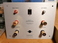
Regarding the build process itself, I only have a few notes:
Screws for the power plug was missing. Sourced some locally.
The supplied 7ml of heat paste wasn't enough for me to get full 'seapage' around the bracket, so I cleaned it off and used 10ml of my own stuff.
Added washers to the screws holding the filter board. Heads were too small for the holes in the bottom.
Used the srews from the lid/bottom of the chassis to hold the TO-3 brackets. They are 2mm shorter.
Used the screws from the TO-3 bracket for the lid/bottom of the chassis.
I found no need for adding washers to avoid bending of rear chassis.
If you just slide the 'rails' on the heat-sinks all the way to the back so it touches the rear chassis before tightening the screws in the heat-sinks, the problem doesn't occur.
Somewhere along the line, probably in this thread, 'zomeone' wrote the following statements:
1: Lottery amp is M2 for sissies, and...
2: M2 is Firstwatt totem!
I guess it's time to start building an M2.
Sorry I didn't write earlier, but I've been hypnotized, pure and simple.
This is a very happy little amp, very eager to convince you that the way it plays music, is the way it's meant to be played. It's so excited, it occasionally feels like it's sprinkling a little fairydust over the top, just to impress you.
The silence, the expansion, the dynamics are nothing short of amazing. It just urges you to keep on listening.
I absolutely love it. A true gem! Huuuuge thank you to papa and everyone involved in making this possible.
Regarding the build process itself, I only have a few notes:
Screws for the power plug was missing. Sourced some locally.
The supplied 7ml of heat paste wasn't enough for me to get full 'seapage' around the bracket, so I cleaned it off and used 10ml of my own stuff.
Added washers to the screws holding the filter board. Heads were too small for the holes in the bottom.
Used the srews from the lid/bottom of the chassis to hold the TO-3 brackets. They are 2mm shorter.
Used the screws from the TO-3 bracket for the lid/bottom of the chassis.
I found no need for adding washers to avoid bending of rear chassis.
If you just slide the 'rails' on the heat-sinks all the way to the back so it touches the rear chassis before tightening the screws in the heat-sinks, the problem doesn't occur.
Somewhere along the line, probably in this thread, 'zomeone' wrote the following statements:
1: Lottery amp is M2 for sissies, and...
2: M2 is Firstwatt totem!
I guess it's time to start building an M2.
Attachments


@ Baeijsman
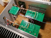
Very tight wiring, fantastic work Congratulations
Vfet SE is excellent on medium and highs,
build bi-amplification audio system with Pass active crossover, DIY Biamp 6-24 Crossover – diyAudio Store
Pass AB 100W amp for the woofers AB100 Class AB Power Amplifier
and You have much more satisfaction with this solution than build and use M2 alone
Very tight wiring, fantastic work
Congratulations..I guess it's time to start building an M2.
Vfet SE is excellent on medium and highs,
build bi-amplification audio system with Pass active crossover, DIY Biamp 6-24 Crossover – diyAudio Store
Pass AB 100W amp for the woofers AB100 Class AB Power Amplifier
and You have much more satisfaction with this solution than build and use M2 alone
@ baeijsman
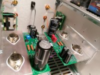
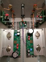
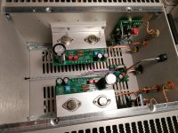
Thanks for sharing. Today I was planning out the layout for the boards on the heat sinks and noticed your layout to be the same. 6L6's build guide has both boards closer to the front of the chassis. I much prefer them closer to the rear to minimize extra wiring length. Likewise in my other VFet amp, I don't like bird nests.
Interestingly, i'm missing the small nuts for the power socket but have the screws. Will check for a local option.
Yes, very nice build and wiring.
Can see VFET brackets are moved to the center of heatsinks. Were there holes that just fit this position?
Build guide suggest that brackets are moved to the front. It causes that heatsink are a lot hotter at one end than the other......but still "only" 50C max. Then 10mm front panel takes its part also......
From what I understood, the reason for moving the brackets towards the front, was to ensure enough room for the alternative front-ends, but as I have no intention of changing it, I thought it made more sense to place them closer to the centre. No additional drilling/tapping was nessesary.
- Home
- Amplifiers
- Pass Labs
- DIY Sony VFET pt 1