Good Morning!
Number 108 is on the bench. I have the whole day all to myself. Really looking forward to tha day.
Number 108 is on the bench. I have the whole day all to myself. Really looking forward to tha day.
Enjoy your day!
I did manage to finally get the parts boxes on my bench last night.
Seems like the only wiring I’ve done lately is for recessed lighting in the kitchen and sunroom renovation I’m bogged down in...exhausting and not near to being finished.
I did manage to get my F2J monoblocks back together...the fans I installed for cooling were cheap and got too noisy.
Also got my hypex amps functional for bass duty.
So now the “queue” is clear for me to start the VFET.
Going to print out the schematic later and try to get started.
Hello,
it´s time to post some pictures of Nr.107 and bring it back to page no.1 🙂
But at first I have to thank my friend Gerd (generg) and Mr.Pass to give me the opportunity to build this amp.
At the end of my DIY-Career it´s perfect for me (I build AJ, M2, J2, XA30/60.5/8, XA25, F5 Turbo, F6, F7, a lot XP Pres/Phonos, HPA, SIT-1, ...)


The VFET sounds pretty good in different setups!
In my opinion the VFET sounds better with a tube pre amp (I have a lot of them diy as well).
What I(!) don´t understand if somebody complains about missing screws or cables.
In my opinion everybody who build an amp should have enough cables or screws in his drawers.
Some guys will see that I took different feets (diy at a lathe) I don´t like plastic feets and I never use the screws of Modushop.
This amp give me the motivation to start my open baffle project with University 312 triaxial chassis which are still in my cellar 😉
Kind regards
Andreas
Hello Dan,
a special version of Speakerheaven Network 5.0.
I go to them since more then 30 years and they bulid what I want 🙂
Speaker Heaven, Ihr High-End-Lautsprecher, Klangmöbel, Lautsprechersysteme Spezialist aus Duisburg
There are not a lot companies on the market who can handle ceramic chassis.
They can!!!
By the way the it´s a diamond tweeter 🙂
This Speaker works awesome with 300B, El34, SIT-1, ...
Kind regards
Andreas
Last edited:
Hello,
it´s time to post some pictures of Nr.107 and bring it back to page no.1 🙂
But at first I have to thank my friend Gerd (generg) and Mr.Pass to give me the opportunity to build this amp.
At the end of my DIY-Career it´s perfect for me (I build AJ, M2, J2, XA30/60.5/8, XA25, F5 Turbo, F6, F7, a lot XP Pres/Phonos, HPA, SIT-1, ...)
The VFET sounds pretty good in different setups!
In my opinion the VFET sounds better with a tube pre amp (I have a lot of them diy as well).
What I(!) don´t understand if somebody complains about missing screws or cables.
In my opinion everybody who build an amp should have enough cables or screws in his drawers.
Some guys will see that I took different feets (diy at a lathe) I don´t like plastic feets and I never use the screws of Modushop.
This amp give me the motivation to start my open baffle project with University 312 triaxial chassis which are still in my cellar 😉
Kind regards
Andreas
These are my favorite feets.
40x20mm Aluminum HIFI AMP Speaker Isolation Stand Turntable DAC Feet Pad Black*4 | eBay
Regards,
Dan
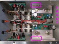
For builders who are considering possibly installing one or more of the other front end cards, I recommend that you plan to position your VFET sub-assembly on the heatsink exactly as member andreasw exhibited in post #1183 above.
Scourge, Bulwark, Marauder, and Dreadnought all have larger PCBs than the Toshiba JFET front end cards that were included in the kit. These other boards fit correctly on the UMS drilled heatsink when placed exactly where he shows.
_
Scourge, Bulwark, Marauder, and Dreadnought all have larger PCBs than the Toshiba JFET front end cards that were included in the kit. These other boards fit correctly on the UMS drilled heatsink when placed exactly where he shows.
_
Attachments
Actual progress...
Nothing here anyone hasn’t seen...still, its great for me given renovations and everything I’ve got going on.
This has actually been the most relaxing thing I’ve worked on in ages.
It got up to almost 90 F here yesterday and today, so I took some time off.
The whole concept of an “Amp in a box” is wonderful and brings me back to my childhood when I used to spend a bit of time in my parents basement building model airplanes and other projects during my summer vacation.
I probably won’t be done any time soon, but I’ll enjoy every minute of my “quiet time”
Attachments

For builders who are considering possibly installing one or more of the other front end cards, I recommend that you plan to position your VFET sub-assembly on the heatsink exactly as member andreasw exhibited in post #1183 above.
Scourge, Bulwark, Marauder, and Dreadnought all have larger PCBs than the Toshiba JFET front end cards that were included in the kit. These other boards fit correctly on the UMS drilled heatsink when placed exactly where he shows.
_
“Follow the plan”, got it. There could be additional input cards by the time round 3 comes out, later this year, which I hope to participate in. Thanks for the tip Mark.
There already are more front end cards. Some but not all of them have been shipped to reviewers for listening evaluation.
If we set aside people named Nelson or Mark, nobody else has built any of the first four (so far!). Accordingly there is no urgency to uncloak others. All in good time.
If we set aside people named Nelson or Mark, nobody else has built any of the first four (so far!). Accordingly there is no urgency to uncloak others. All in good time.
My plan is to build the Dreadnought. Thought that might be an interesting contrast to the stock FE. I should have the pcb's very soon. Parts are on a Mouser order with some backordered stuff. (I did acquire some KSA1220's at least) So it's just a waiting game right now..
Actual progress...
I've been slacking! That's way more progress than 064. All I've done is deburr the heatsinks and partially assemble the chassis...

Parts are on a Mouser order with some backordered stuff. (I did acquire some KSA1220's at least)
I have informed the person assembling the kits that I have the semis
in question in quantities (no surprise), so that will not be the problem.
I’m interested in the Bulwark and Dreadnaught cards, but currently have another project entering final assembly.
For builders who are considering possibly installing one or more of the other front end cards, I recommend that you plan to position your VFET sub-assembly on the heatsink exactly as member andreasw exhibited in post #1183 above.
Scourge, Bulwark, Marauder, and Dreadnought all have larger PCBs than the Toshiba JFET front end cards that were included in the kit. These other boards fit correctly on the UMS drilled heatsink when placed exactly where he shows.
I don't quite get this (maybe it's because I still have not received my parts kit, so I cannot look at the parts and boards...). What exactly are you trying to show with the purple rectangles? I don't see anything interesting there.
Hi,
There is a (one) recommended way to position the OS boards, and that is "closest to the front panel".
Due to the heatsinks having several bores to attach them, there are though other ways to position the OS boards, more to the center. Some went this route for whetever reason they liked (supposed better heatspread, shorter wires etc.). Various combinations with the OS and also FE positionings are possible with the provided boards.
My understanding is Mark points that all this might be Ok with the provided boards, but the other FE boards he designed might not stick to the same form factor and hence should you want to try these tempting FE boards you might be limited unless you undo what you did if not positioning the OS boards correctly. Read some FE boards require more space.
Mark outlined in purpple the recommanded mountings of the OS board, which enable compatibility with current and presumably further developments as this positioning is the one that leaves the most space.
I hope this helps
Claude
Last edited:
I have six 2sk60 and seven 2sk18. I thought about the craziness again of putting one of these into a defunct Sony TA 4650 chassis with a Korg gain. From circuit power supply diagram, preamp voltage rail is 20V, it looks like push pull amp stage rails aare 38v and -38v. Heat sink is for high bias AB 30 watts two channels, so should be OK for 10 watts class A, already slotted for two transistors per channel. Anode dissipation of lesser VFET parts 2sk60/2sj18 is still 60 watts, so should be OK for 10 watts class A. I suppose use one half rail of rectified 38v for of each channel and leave the other channel ungrounded.
Just dreaming, it would be a nice nostalgia build. I don't think I have the chops, though, don't even know if concept is viable.
Just dreaming, it would be a nice nostalgia build. I don't think I have the chops, though, don't even know if concept is viable.
If I compare the one heatsink in my TA 4650 to the two sinks 4U/300 of the DIY Sony VFET - the little heatsink in the TA 4650 is way too small to support Class A operation.
Also, I just had a look into my copy of the TA 4650 service manual - bias for the VFETs seems only to be about 160 mA in that amp.
Regards, Claas
Also, I just had a look into my copy of the TA 4650 service manual - bias for the VFETs seems only to be about 160 mA in that amp.
Regards, Claas
I don't quite get this (maybe it's because I still have not received my parts kit.
Do you have tracking number ? Why such long time ?
Maybe they are in Swiss customs office or..etc.?
Any informations wher are your parcel today : airport ? Still in transit ??
- Home
- Amplifiers
- Pass Labs
- DIY Sony VFET Builders thread