We need a “How I modified my VFET amp”.
I'll definitely subscribe to such a thread.
This is also that thread 😉
Edited to add:
There are already five or six alternate front end cards to try. This is also a good place to discuss those, if the builders wish to.
Edited to add:
There are already five or six alternate front end cards to try. This is also a good place to discuss those, if the builders wish to.
Last edited:
Looks good!
Soundhappy, thanks for reminding me of that album. I need to rotate that into my playlist again.
It sounds wonderful with a great N.P. amp.
Looks like you have put together another tidy build.

Thanks Codyt and TungstenAudio 😀
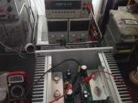
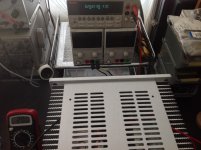
First time music play with Vfet SE was this baroque with the choir voices
Jordi Savall - Les 'Magnificat' de Vivaldi et de Bach, la 'Suite pour orchestre ndeg3' de Bach et les 'Jubilate Deo' de Lully on Vimeo
Bias is stable like a Himalayan mountains
Attachments
I have not done it yet.
Could you get the shims in without unscrew the power connector (as bottom cover needs to be removed) and loosen the front panel screws to release tension?
I estimated it to be too much work for the time being 🙂
I simply removed the top, removed the screws holding the back panel, inserted washers between the panel and the bracket. Put everything back together. Problem solved.
Ok.....if it can be done without removing the bottom panel where SMPS filter is mounted it may be doable without spending too much time.
I'll definitely subscribe to such a thread.
More : how to perfectly tailor my amp to the speaker it drive 😎.
I just turned off my Sony VFET amp for the first time since I increased the supply bypass caps to 1000 uF. Guess what, no thump. It was pretty slight before, but now it’s gone.
Which cap are you talking about can you give the number? Are you talking about the first cap in the CLC?
What is the power rating on this amp? Want to know before getting involved in second go around.
I’m referring to the cap that I added to each output stage card. Between V+ and G.Which cap are you talking about can you give the number? Are you talking about the first cap in the CLC?
That sounds good, will follow.I have also experienced similar improvements in soundstage when driving a stereo amp from a common PSU. Adding extra rail capacitance helps to improve stereo channel separation. This can dramatically improve stereo soundstage.
The Mean Well SMPS has an upper limit on the amount of capacitance that can be added. However, this limit can be mitigated with a soft start circuit that slowly opens up the current between the SMPS and the cap bank. Usually through a largish value NTC (circa 30ohms cold) and then after say 2 to 5 seconds a solid state relay (SSR) bypasses the NTC, at which point the caps have already charged and the SMPS is not presented with a huge in-rush that usually would cause it to go into hiccup mode.
I might try this and report back, and of course, will make the circuit design and Gerbers freely available.
^ Those are probably more heroic measures than necessary. I simply added a 1000 uF, 50V capacitor between the V+ and G of each output stage card. (Panasonic FC series, but any good Nichicon KW, KA or KT will also work well) I have not made any other changes to my amp. The earlier 440 uF caps were removed and replaced by these.
The same cap that improved the sound of my amp also eliminated the turn-off thump.
The same cap that improved the sound of my amp also eliminated the turn-off thump.
More : how to perfectly tailor my amp to the speaker it drive 😎.
It makes more sense to match the speaker to the amp since we are talking about few degrees of freedomw with this specific amplifier.
What speakers do you have? What doe sthe impedance look like?
dave
You are right in the case you want to build your system around this design. My remark was more for the person who want the build a system from scratch.It makes more sense to match the speaker to the amp since we are talking about few degrees of freedomw with this specific amplifier.
What speakers do you have? What does the impedance look like?
dave
Perhaps I've missed it, but has anyone had a chance to compare the Sony DIY SE amp with a SIT-2? It would be interesting to see how the common drain and signal iron compare to the common source topology.
Hi guys!
A question about the schematic and kit parts. With the kit there came 4 pcs of 100 ohm resistors - R3 and R4 according to the schematic (Output stage).
But on the PCB I can't find R3? Is it already soldered - nearest to the bracket (and IRF250) in the same line as R8?
A question about the schematic and kit parts. With the kit there came 4 pcs of 100 ohm resistors - R3 and R4 according to the schematic (Output stage).
But on the PCB I can't find R3? Is it already soldered - nearest to the bracket (and IRF250) in the same line as R8?
Last edited:
Yes R3 came pre installed. See BOM R3 has a * next to it which indicates it's pre installed. R6 on my board was also pre installed. I had 2 100 ohm resistors leftover.
Last edited:
Thanks! I read the article but somehow missed the BOM...😉
But also - according to the BOM R6 shouldn't be installed but it seems it is..? Just checking...
But also - according to the BOM R6 shouldn't be installed but it seems it is..? Just checking...
Last edited:
- Home
- Amplifiers
- Pass Labs
- DIY Sony VFET Builders thread