So basicaly similar to trippling the initial 1000uF value of C1 on the PS board.
Not taking into account it is done directly on each OS board which might yeld further benefits as closer to the loads.
Claude
Not taking into account it is done directly on each OS board which might yeld further benefits as closer to the loads.
Claude
Quote: Why only 1kuf then?
Will leave the OP reply... but I would say that trippling the intial value is already taking a gamble on the SMPS' ability to drive extra C, plus trippling what Papa deemed adequate is probably overkill. The OP reported it worked very well, why more (diminishing returns, no linear improvement & Co...)
Claude
Is it possible to measure a significant difference in modulation of the 36 VDC with and without the 1000uF cap during playing?
If not it would be difficult to give an objektive explanation of why the extra caps can change stereo imaging to be better?
If not it would be difficult to give an objektive explanation of why the extra caps can change stereo imaging to be better?
You can measure stereo separation very easily. Apply signal to one channel and measure the signal on the other. If you can hear it without any special equipment, it is rather low. On SE Class A amps, they have poor PSRR, the "noise" in the power supply rails will make it out as sound. So if this noise is the modulation of one channel onto the other, it decreases the stereo separation. In my experience, when stereo separation is less than 60dB, soundstage degrades. Ideally we want something in the 80-90dB or more separation. This is where dual monoblocks shine.
Having said that, the Sony VFET in stock form has no easily audible stereo cross talk (on my 83.db speakers, YMMV on 103dB sensitive horns). That is, plug the input into the right channel (disconnect right output) and press your ear to the left speaker cone. It is quiet. Something may show up on an FFT with -130dB noise floor, but as a basic check, it is not an issue.
Having said that, the Sony VFET in stock form has no easily audible stereo cross talk (on my 83.db speakers, YMMV on 103dB sensitive horns). That is, plug the input into the right channel (disconnect right output) and press your ear to the left speaker cone. It is quiet. Something may show up on an FFT with -130dB noise floor, but as a basic check, it is not an issue.
Last edited:
In the Pch VFET amp, the output stage's supply current is constant and does not change when there is signal present. There is no "modulation" of supply current. Supply current is constant.
Additionally, even if you hypothesize that there exists some kind of unwanted, non-DC signal on the power supply, the only way for that unwanted signal to get to the loudspeaker output, is through the output stage's current source. But the current source is a very, very high impedance. As are all current sources. So there exists a voltage divider from supply to output: the high impedance of the current source, fights against the low impedance of the loudspeaker.
Following standard voltage divider math, a hypothetical signal on the power supply is attenuated by (Zspeaker / (Zspeaker + Zcurrentsource)). Zspeaker is around 8 ohms and Zcurrentsource is around 2000 ohms, in fact, probably a lot more. For every millivolt of noise on the supply, (8/2008) = 4 microvolts of noise appears across the loudspeaker.
Putting them together: the amount of noise (or "other channel modulation") on the supply, Vsupplynoise, is zero. And the amount of noise at the loudspeaker, Vspeakernoise, equals Vsupplynoise times (8/2008).
Vspeakernoise = 0 x (8/2008) = 0.
Quote: Why only 1kuf then?
Will leave the OP reply... but I would say that trippling the intial value is already taking a gamble on the SMPS' ability to drive extra C, plus trippling what Papa deemed adequate is probably overkill. The OP reported it worked very well, why more (diminishing returns, no linear improvement & Co...)
Claude
I was kinda sarcastic 🙂 Nelson, for example, reported a good result with no additional 1000uf. Speaking of diminishing returns 😉
But as ZM mentioned we all have our own pair (of ears. just in case) and hear differently.
If you ask me(though nobody does 🙁 ), the big plus of the kit was that it eliminated a lot of anxiety about part selection: all as Nelson ordered 🙂
Thanks for the analysis, Mark. If does seem very immune to channel crosstalk modulation. I wonder what channel separation is though in dB?
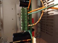
Can see your back panel also bends inwards a bit. On the larger chassis a shim behind the 4 screws (between panel and heatsink) cured it. But don't know if I will disassemble to make this modification. Forgot it to do it from start....
Interesting that the front panel gets as hot as the heatsinks even that there are no paste between heatsink and front panel.
Placed 4 washers between the back panel and the brackets. The back panel is now straight. The heatsink is slightly longer than bracket causing the back panel to bend when tightening the screws. I did not shim the front panel as I wish to retain the thermal coupling between the front panel and the heatsink . If I ever remove the front panel I will put some thermal grease between the two.
as I'm often saying, I tend to overkill because that makes me feeling smarter, and I have broader Green
though, what also makes me feel smarter - that I'm investing in bigger hardware, not more expensive wires or fancy dressed caps
and I like to revitalize speaker cones with Dammar
it's fun ....... while nothing wrong with having deeper knowledge what's under the hood
if nothing else ( by logic that knowledge is best embraced when gotten with scull actually hittin' that concrete wall) experimenting should bring conclusions what's beneficiary and what isn't - with time
Experimentation is a young persons task, for the older person it's more confirmation than exploration.
Which is good, skull against concrete can hurt.
Which is good, skull against concrete can hurt.
I recall that the M2 would take about 45 seconds to slowly charge up to reach its steady state bias current and did not have a turn on or off thump issue. I was expecting the VFET to behave similarly but the turn on was almost instantaneous as I monitored bias current. I think it’s the RC time constant of R5+R7 and C2. It’s about 4s for the VFET vs about 115s for M2. I wonder if Mr Pass or ZM could suggest a longer setting here or are there other considerations at play? Making C2 3300uF would slow down the thump by 3x.
I was similarly thinking reduced C3 (470uF) or larger C1. I have a barely there thump so no issue for me though.
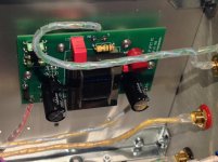
These terminal blocks are 6.35. You will need to install the C4 on the bottom. In my case I used 5mm blocks underneath so I can try different input caps.
TE Conectivity 796740 green 10g 6.35mm
TE Con 282836 green 16g 5mm
These blocks have brass top screw instead of magnetic steel ones
TE Conectivity 796740 green 10g 6.35mm
TE Con 282836 green 16g 5mm
These blocks have brass top screw instead of magnetic steel ones
Attachments
Amazing Papa 
It's alive new born Vfet SE amplifier sings in the middle of the night
Massive Attack - Teardrop (Lyric Video) on Vimeo
Sublime Thanks Mr. Pass & DiyAudio Team & Modushop
Edit: All photos tomorrow.. Kind regards
It's alive new born Vfet SE amplifier sings in the middle of the night
Massive Attack - Teardrop (Lyric Video) on Vimeo
Sublime
Thanks Mr. Pass & DiyAudio Team & ModushopEdit: All photos tomorrow.. Kind regards
Attachments
I just turned off my Sony VFET amp for the first time since I increased the supply bypass caps to 1000 uF. Guess what, no thump. It was pretty slight before, but now it’s gone.
Soundhappy, thanks for reminding me of that album. I need to rotate that into my playlist again. It sounds wonderful with a great N.P. amp.
Looks like you have put together another tidy build.

Looks like you have put together another tidy build.
Placed 4 washers between the back panel and the brackets. The back panel is now straight. The heatsink is slightly longer than bracket causing the back panel to bend when tightening the screws. I did not shim the front panel as I wish to retain the thermal coupling between the front panel and the heatsink . If I ever remove the front panel I will put some thermal grease between the two.
I have not done it yet.
Could you get the shims in without unscrew the power connector (as bottom cover needs to be removed) and loosen the front panel screws to release tension?
I estimated it to be too much work for the time being 🙂
Was missing a part of VFET amp and had a dent on one of the heat sinks. Modushop replied promptly and sent the part and a replacement heat sink.
Great service.
Thanks Gianluca / Modushop! 🙂
Great service.
Thanks Gianluca / Modushop! 🙂
- Home
- Amplifiers
- Pass Labs
- DIY Sony VFET Builders thread