But he shouldn’t be BBQing his preamp with the amp! The amp is light enough to be on top
Great news! Looking snazzy next to that turn table... 😎
Last edited:
Hmmm, can you maybe provide a link or similar to Nelsons explanation?
If an isolated supply was used, what's the point of isolating the chassis from audio GND using a thermistor?
Also, if a supply without isolation is used, the audio GND is connected to mains earth, which may cause ground loop troubles. It would be better to go with an isolated unit.
Amps with isolated supplies can still benefit from reduced noise pickup when grounded to mains earth ground through a ground loop breaker or NTC. Examples of this are preamps or phono stage preamps that pick up EMI hum when you touch the chassis or volume knob that is not grounded. Once you ground it, the noise pickup goes away.
Sure. But if the MeanWell brick is isolated, the VFET chassis cannot have a connection to mains ground.
Hmmm, can you maybe provide a link or similar to Nelsons explanation?
If an isolated supply was used, what's the point of isolating the chassis from audio GND using a thermistor?
Also, if a supply without isolation is used, the audio GND is connected to mains earth, which may cause ground loop troubles. It would be better to go with an isolated unit.
https://www.diyaudio.com/forums/pass-labs/370689-diy-sony-vfet-builders-thread-33.html#post6626426
Also see roughly 10ish to 20ish preceding posts. I may have misinterpreted the explanation.... could be highly likely. 😀
Sure. But if the MeanWell brick is isolated, the VFET chassis cannot have a connection to mains ground.
Correct... to the best of my knowledge. However... there was a later post that I can't seen to find... that stated the Meanwell supply had the appropriate safety rating to allow the VFET to "float".
Sorry that I cannot find that exact post.... if it turns up, I'll post. Again... as with any of my posts, I can't claim to "know", but I can usually piece a few things together from those that do, remember them in pieces and completely mess up the original intention. 😀
The
Thermistor and lug/wire are there for the situation where the V- on the supply is
isolated.
That makes sense, assuming the shield is connected to mains ground, but not to V-.
I would be surprised if those power supply bricks would be wired in many different ways. I guess I'll wait for mine to arrive and then figure it out on my own.
My WAG is that the circuit / boards were quite possibly finalized before the specific Meanwell supply was sourced. Having the possibility to go both routes allowed flexibility in choice.
The Meanwell's that come with the kits "should" all be the same unit.
The Meanwell's that come with the kits "should" all be the same unit.
Last edited:
The power supply brick -ve are connected to the brick cable shield and brick male plug metal sleeve,that is for sure.Maybe someone can measure and see if the metal sleeve and hence the -ve's are connected to brick "U" ground. If that is the case then i don't understand the redundant explanation.On normal FW bipolar supplies the board commons are brought thru a thermistor and tied to the chassis which is also tied to the "U" ground.If the sleeve,-ve,and cable shield is actually connected to the "U" ground then the way this is set up the chassis is isolated from "U" ground via the thermistor and the board "G" are directly tied to the "U" ground.That sound backwards to what the normal FW setup is.That makes sense, assuming the shield is connected to mains ground, but not to V-.
I would be surprised if those power supply bricks would be wired in many different ways. I guess I'll wait for mine to arrive and then figure it out on my own.
Apologies... not sure what "U" GND is. Is that another nomenclature for mains earth? If so, then the answer is yes. Previously confirmed. If not, happy to measure with a bit more information re: what is the meaning of "U" GND.

Ok yes the "U" ground I talk about is mains earth(the round terminal in the 3 prong plug).So the brick mains earth"U" ground is confirmed to be connected then to the brick cable shield and thus the -ve teminals.That being the case then the way many of the the setups posted now (without connecting the additional terminals on the panel connector to chassis) then the chassis is actually isolated from safety"U" ground because of the thermistor.Now if the additional panel connector terminals are connected to the chassis as the colored wiring diagram shows then the chassis is connected directly to safety "U" ground as are the board "g" terminals and the thermistor is shorted out and the board "g" terminals are not isolated from "U" ground like a normal FW bipolar supply is.I hope i'm making sense here to you.Either way something is not right with this setup.Not having the chassis directly connected to "u" ground is not good and having the thermistor shorted out can't be right,why is it even there then? I hope someone with more brain power can try and explain how the way this is is O.K. and why.
My wandering eye...
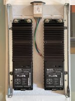
I just can't help myself. For better or worse, I'm still stuck on an internal power supply. After mocking up 2nd chassis ideas in CAD, I'm not really feeling the aesthetics are working out... 1U chassis too short, 2U chassis too tall, when stacked with the V-FET chassis. So, it's back to internal.
These twin cuties caught my attention... hauled them out of the "surplus acquisitions" box. Very expensive new, but sometimes you can snag them surplus at fire sale prices. Pure coincidence, but these ones are just the right voltage. I'll test them out carefully and see if they're up to the job or not. And not to worry about blocking the ventilation - I'd mount them on some standoffs to create an air gap for good flow from the slots underneath.
If I go with these dual-mono supplies, then I'll probably design a high-performance filter board for them and will be happy to share. Most likely to employ a quality common-mode choke and meticulous RF layout & component selection for best switching noise suppression.
I just can't help myself. For better or worse, I'm still stuck on an internal power supply. After mocking up 2nd chassis ideas in CAD, I'm not really feeling the aesthetics are working out... 1U chassis too short, 2U chassis too tall, when stacked with the V-FET chassis. So, it's back to internal.
These twin cuties caught my attention... hauled them out of the "surplus acquisitions" box. Very expensive new, but sometimes you can snag them surplus at fire sale prices. Pure coincidence, but these ones are just the right voltage. I'll test them out carefully and see if they're up to the job or not. And not to worry about blocking the ventilation - I'd mount them on some standoffs to create an air gap for good flow from the slots underneath.
They are very quiet, but not as quiet as the VFET. Hoping for a higher-power SMPS filter concept from Mr. Johnson...
If I go with these dual-mono supplies, then I'll probably design a high-performance filter board for them and will be happy to share. Most likely to employ a quality common-mode choke and meticulous RF layout & component selection for best switching noise suppression.
Attachments
Ok yes the "U" ground I talk about is mains earth(the round terminal in the 3 prong plug).So the brick mains earth"U" ground is confirmed to be connected then to the brick cable shield and thus the -ve teminals.That being the case then the way many of the the setups posted now (without connecting the additional terminals on the panel connector to chassis) then the chassis is actually isolated from safety"U" ground because of the thermistor.
I believe that to be correct, and that was why I had asked the original question. The answer was/is that the Meanwell supply has the appropriate safety rating to allow this type of configuration.
That is why I left those connections out when armed with the information above that it was in-fact safe.Now if the additional panel connector terminals are connected to the chassis as the colored wiring diagram shows then the chassis is connected directly to safety "U" ground as are the board "g" terminals and the thermistor is shorted out and the board "g" terminals are not isolated from "U" ground like a normal FW bipolar supply is.
I hope i'm making sense here to you.Either way something is not right with this setup.Not having the chassis directly connected to "u" ground is not good and having the thermistor shorted out can't be right,why is it even there then? I hope someone with more brain power can try and explain how the way this is is O.K. and why.
You posed excellent questions, similar to my own, which... I think... were answered. If you have an isolated supply, then use the "additional" wiring tying the mains earth GND to chassis along with -Ve separate from the supply as shown in the diagram. If you have a PSU like supplied with the kit, then there is no need (and possibly a detriment?) to adding the additional wiring b/c it will in-effect be similar to the schematic I posted earlier in the thread.
Whether or not the wiring diagram should be updated to reflect the use of this particular Meanwell supply .... I don't know.
What I can generally rely upon is that some noodling in my wee brain along with not seeing that particular wiring in 6L6's build guide... gave me confidence to leave it out.
Still a great discussion. Anything that causes confusion as it relates to safety concerns in-particular should be discussed openly before building. Just IMO.
Still and all, an absolutely amazing guide and amplifier. If all we have is a few tiny questions remaining and a lot of successful builds, then woooo hooo.
Mark has a 5A version in the works. Initial testing shows incredible results.
Excellent!! Is there a thread here on this yet?
Given the strengths of this little amp, Nelson's larger Sony VFET amplifier must be amazing.
Scott
This is going to be extremely interesting to me. What sonic effects (if any) would the larger Tokin SITs have compared to the Sony...?
Is it going to be the same, but just... More?
Or, is it going to be more like a brute... Losing some of the 'intricacies' and 'finesse' the smaller SITs may have...?
I suppose I could dig through some of the posts from people who are already using them to try and get an idea. Lol
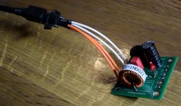
Soldering the power connector required a bit of patience. To be sure I mounted it correct I attached the Meanwell and measured the output voltage on the filter board (36.2 VDC). Also the red LED "worked". I dim everything so I do not install a LED at the front. But I can always look down in the amp if I am "in doubt". I switch everything on at a central place so I also do not use the on/off switch (bypassed on filter board). Then I don't need to think about the longtime DC-current performance of such a tiny switch 🙂 .....but I installed it to "fill out" the hole.....
Attachments
So,with the brick we have either you get a chassis solidly grounded to the "U" ground or you get a chassis that is floated,depending if you put the additional wire from the extra panel terminal to the chassis (solid ground) or not(floating chassis),take your pick.I believe that to be correct, and that was why I had asked the original question. The answer was/is that the Meanwell supply has the appropriate safety rating to allow this type of configuration.
That is why I left those connections out when armed with the information above that it was in-fact safe.
You posed excellent questions, similar to my own, which... I think... were answered. If you have an isolated supply, then use the "additional" wiring tying the mains earth GND to chassis along with -Ve separate from the supply as shown in the diagram. If you have a PSU like supplied with the kit, then there is no need (and possibly a detriment?) to adding the additional wiring b/c it will in-effect be similar to the schematic I posted earlier in the thread.
Whether or not the wiring diagram should be updated to reflect the use of this particular Meanwell supply .... I don't know.
What I can generally rely upon is that some noodling in my wee brain along with not seeing that particular wiring in 6L6's build guide... gave me confidence to leave it out.
Still a great discussion. Anything that causes confusion as it relates to safety concerns in-particular should be discussed openly before building. Just IMO.
Still and all, an absolutely amazing guide and amplifier. If all we have is a few tiny questions remaining and a lot of successful builds, then woooo hooo.
It's audiophilia nervosa 😀
Strikes again!
Attachments
- Home
- Amplifiers
- Pass Labs
- DIY Sony VFET Builders thread