This one is for jamie, (if you already haven't a solution). I had a problem w/ the psone's connector untill I went to digi-key. I purchased one 30 conductor .5mm flat cable (from parallax) then I bought 2 connectors of the same type as on the psone's lcd connector. After this I soldered together the 2 connectors. this I did by soldering the two sets of pins (pcb end) pins together, then used solder wick (or a solder sucker) to remove the excess solder. Then I glued this contraption (sp?) to a piece to a small peice of plasic for duribility. Its neat though you can plug the lcd into one side of the double connector then the flux?connector cable in to the other side and the other end to the flux cable into the psone's driver board.
I was forced into doing this for worries that the flat pcb on the lcd screen would be runined by my moving it around. It's a very nervy job. I had to check all the connections on this extention cable with a strong 10x eyepeice. it's too small to do with a DMM. I've had no problem so far.
I was wondering, can one use the psone's lcds backlight as a fresnel for a OHP lens or do I have to dismattle it and buy my own fresnel?
"I was wondering, can one use the psone's lcds backlight as a fresnel for a OHP lens or do I have to dismattle it and buy my own fresnel?"
Yours has a fresnel between the lcd panel and backlight? Mine had silver sheets that dispersed the light and a thick piece of plastic with a grid etched into it. In order LCD> 3 silver colored like 50% transparent sheets> Thick plastic grid piece> backlight. Now when I use those pieces together or individually I get a more even lighting but alot dimmer one as the sheets of silver colored stuff also reflect alot of light if you look at them. A fresnel is much better but mine didnt have this. Anyone else get a fresnel on their psone lcd? I know the projector panels have them due to the OHP use. What brand is yours? Mine is the Interact Mobile one.
Since a couple of people are useing these panels (and they do work pretty good) I think we should try to form a data base of them as far as how good they look (res. etc), and how dificult to move driver board out of way. Mine had a 1" ribbon aswell but used a stacked mobo type of method (one over the other) so it didnt matter. This would be good to know. And there is only what, maybe 10-12 of these anyhow. Couldnt be that hard to weed out the bad ones.
🙂
No sorry I was mistaken, my panel has no fresnel. Its just the sony psone 5". I guess we could say with this LCD that, you can add an extra $30.00 cnd and some labor for a 6" extention.
Optics isn't really my stong point (I'm learning). I'm more of an electronics guy. My knowledge of OHP's is mucking around with them in elementary school. What is the perpose of the fresnel in a OHP?
Optics isn't really my stong point (I'm learning). I'm more of an electronics guy. My knowledge of OHP's is mucking around with them in elementary school. What is the perpose of the fresnel in a OHP?
"What is the perpose of the fresnel in a OHP?"
To help gather the light from the light source and then send it in a parallel beam formation through the stage (like where you put lcd panel)....They are actually two fresnels back to back against each other and the rigid sides facing each other-( I think the ridged sides face). This shortens the focal lenght to 50% of the one lens. So if they had to have the light source 11" away (F1) then two of the same lenses like this now the light can be 5.5" away from light and still be at focal point.😉
To help gather the light from the light source and then send it in a parallel beam formation through the stage (like where you put lcd panel)....They are actually two fresnels back to back against each other and the rigid sides facing each other-( I think the ridged sides face). This shortens the focal lenght to 50% of the one lens. So if they had to have the light source 11" away (F1) then two of the same lenses like this now the light can be 5.5" away from light and still be at focal point.😉
Tinker, Havok,
still confusion about OHP.optics...
fresnel lenses in OHPs are classical condensor lenses, which are imaging a point light source into projection objective. No parallel light after the stage of OHP! It's a converging light cone and it's apex is at the objective's plane. If the outgoing light from OHP's stage was parallel, most of the light wouldn't reach the objective!
xblocker
"If the outgoing light from OHP's stage was parallel, most of the light wouldn't reach the objective"
OK I see what you are saying. But if you flip a fresnel so rigid side is out (not facing light)doesnt that make light parallel. I see what you mean about the objective and the fresenel focusing light into a cone as thats how my projector works that I built. I have the LCD right where the cone is the size of the panel so as to evenly light it.
OK I see what you are saying. But if you flip a fresnel so rigid side is out (not facing light)doesnt that make light parallel. I see what you mean about the objective and the fresenel focusing light into a cone as thats how my projector works that I built. I have the LCD right where the cone is the size of the panel so as to evenly light it.
Tinker said:But if you flip a fresnel so rigid side is out (not facing light)doesnt that make light parallel.
Again, a fresnel with one sided grids is the same as a planconvex lens and acts this way. If parallel light comes out or not depends of the distance to the light source, and when this distance = focal length, then you have parallel light, no matter which side faces the light source. If the distance > FL then you get a converging light cone, that means, the light source will be imaged in the projection plane (not screen plane!), again depending of how much the distance light source - fresnel is > FL. In reallity in an OHP are two imaging systems:
1. Light source is imaged on objective.(light path)
2. LCD is imaged on screen.(image path)
xblocker
So I should have for my home brew box the following?
Light source at FL(1) in my case 11.5" and this will image the source onto the lcd. The distance of lcd to fresnel should be where the light source covers the entire lcd but should it be before fl or just after fl of fresnel (other side of source focal lenght)-thats my confusion now! Thanks you have been a BIG help explaining this. Fresnels were a mistery to me and optics isnt my bag of tea so to speak. Electronics I can handle (not greatly though) but this stuff is new to me and trying to learn whatever I can from you guys as you have a excellent grasp on this stuff. Thanks again!😀
Light source at FL(1) in my case 11.5" and this will image the source onto the lcd. The distance of lcd to fresnel should be where the light source covers the entire lcd but should it be before fl or just after fl of fresnel (other side of source focal lenght)-thats my confusion now! Thanks you have been a BIG help explaining this. Fresnels were a mistery to me and optics isnt my bag of tea so to speak. Electronics I can handle (not greatly though) but this stuff is new to me and trying to learn whatever I can from you guys as you have a excellent grasp on this stuff. Thanks again!😀
If we are talking about an OHP-like setup, the gap between LCD and fresnel could be ~ 1". Most important is the distance between fresnel and point light source ! This distance can range between 1x to 2x FL to get an converging light cone. The tricky part is to place fresnel/LCD at a plane which is:
1. within 1x to 2x FL of fresnel
2. the resulting light cone must additionally match with the rough FL of the objective.
The LCD will be transmitted from the converging light cone, not from parallel light.
Let's try some examples:
a)If you place the fresnel exactly at 1FL, you have parallel light. No real image of the light source. No magnification.
b)If you place the fresnel slightly over 1FL, the light cone begins to converge in large distance. A real image of the light source will be projected. Big magnification.
c) If you move towards 2xFL, the light cone converges sooner, the real projected image comes nearer. Less magnification.
d) if you place at 2xFL, the light cone has reached it's shortest possibility. The real image of the light source is projected at 2xFL of the fresnel. Magnification=1
And remember, there's only one constellation, where light cone and objective fit together: If the image of the light source falls into objective!
Ufff! Done! (Hard to explain in english)
xblocker
question for xblocker
Hi xblocker, you seem to have a really good grasp of optics, can I bounce this question off you?
I have this setup:
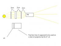
diverging lightsource->two ohp fresnels back to back (really four in total, as each one has two pieces stuck together)->as close as I can get it to the fresnels is the 5" lcd->4" fujinon proj lens about 8mm or so from lcd. The fujinon needs to mounted virtually right on the lcd to focus correctly.
Now the two fresnels converge the light very sharply through the lcd. This is necessary or the fujinon does not project the whole lcd image. However I have noticed that the brightness and general performance of this setup is not as good as my previous setup with just a single fresnel about 20cm after the lcd panel acting as the projection lens.
I am thinking that the reason it is not as efficient is because the angle of light through the lcd is not optimum (far from 90 degrees!). Somebody mentioned the idea of one fresnel before and one fresnel after the lcd to improve this. Do you think it will be possible to use the fujinon compound lens after the second fresnel in this situation?
I would simply try it except I have to physically alter my lcd mounting quite a bit to fit the second fresnel after the lcd.
I hope I have explained this ok, what I mean is:
lightsource->fresnel->2cm->lcd->2cm->fresnel->??mm fujionon compound lens. Thanks for any help.
Hi xblocker, you seem to have a really good grasp of optics, can I bounce this question off you?
I have this setup:
diverging lightsource->two ohp fresnels back to back (really four in total, as each one has two pieces stuck together)->as close as I can get it to the fresnels is the 5" lcd->4" fujinon proj lens about 8mm or so from lcd. The fujinon needs to mounted virtually right on the lcd to focus correctly.
Now the two fresnels converge the light very sharply through the lcd. This is necessary or the fujinon does not project the whole lcd image. However I have noticed that the brightness and general performance of this setup is not as good as my previous setup with just a single fresnel about 20cm after the lcd panel acting as the projection lens.
I am thinking that the reason it is not as efficient is because the angle of light through the lcd is not optimum (far from 90 degrees!). Somebody mentioned the idea of one fresnel before and one fresnel after the lcd to improve this. Do you think it will be possible to use the fujinon compound lens after the second fresnel in this situation?
I would simply try it except I have to physically alter my lcd mounting quite a bit to fit the second fresnel after the lcd.
I hope I have explained this ok, what I mean is:
lightsource->fresnel->2cm->lcd->2cm->fresnel->??mm fujionon compound lens. Thanks for any help.
xblocker is spot on, although sometimes it is easier to show things visually. so oddly enough here are a couple of links to show what he means
this one is a series of simple ray diagrams using a convex lens, which is roughly the same sort of situation with the fresnel
and this one is a nice little javascript applet/animation thingy where you can change the position of the object (lcd) in relation to the focal length of the lens to see the resultant image...
yeah... just click the links, it'll make sense, i swear
MuzzMan,
well, to give an answer about your question, it is required to know more about details.
1. What's the FL of projection lens
2. What's the FL of fresnels.
3. What kind of 'diverging' light you use?
4. How long is the throw distance?
All calculations only make sense if using a point light source. You say, you have a 4" projection lens 8mm away from LCD. Do you mean 4" diameter ? I don't know this fujinon lens, but usually a 4" lens can't have a FL< 4". So i don't understand how it can work at 8mm(!) distance. Either this isn't a common projection objective or it must have some kind of an integrated condensor.
Assumed, the working distance from LCD is really 8mm, this cannot be changed, it's then a precondition of image path to work at all.
And, if this proj. lens indeed has an integrated condensor (field lens), a fresnel between proj. lens isn't needed. Simple said:
FL of proj. lens determins all other optical parameters.
xblocker
xblocker,
muzzman's fuji rear projection lens assembly is for crt projectors. It is made to sit flat up against the crt tube. But it can only capture a 4" image this way. It is deseigned this way as to catch ALL the light from crt....By him setting it at 8mm it now doesnt cop the picture taking it from 5" to 4" missing edges of screen. He wants to know if he did use a condensor lens (like fresnel or real condensor) If he could set the lens assembly closer to the lcd as it is the only way it will focus correctly.🙂
muzzman's fuji rear projection lens assembly is for crt projectors. It is made to sit flat up against the crt tube. But it can only capture a 4" image this way. It is deseigned this way as to catch ALL the light from crt....By him setting it at 8mm it now doesnt cop the picture taking it from 5" to 4" missing edges of screen. He wants to know if he did use a condensor lens (like fresnel or real condensor) If he could set the lens assembly closer to the lcd as it is the only way it will focus correctly.🙂
Attachments
Ok, i got it, now if we state, that the distance between an object (LCD) and objective has to be between 1x FL and 2xFL to get a projection image, then the FL of this fujinon would be smaller then 8 mm. Excellent objectives reach a F-ratio about 1.0 (F/D). If the lens has a D=4", then F could be also 4" to get 1.0. But <8mm??
I don't have the time to calculate this now, but this is physically impossible !! Is it possible to remove the first lens of the objective?
I suppose that the true FL of that lens is more than a few mm. Something like 4,5 or 6". So the most important lenses must sit at the other end of the tube.
On the other hand it could be, the first lens acts as a field lens and do the same job as the second fresnel, but it's too small to get the whole LCD image. If the first lens is removable, you could try to cut the tubus and get a shorter objective with the rest of the lenses and the real focal lenght. The new objective of course is more away from LCD. So you could replace the too small first lens with the second fresnel, assumed it has a FL which is roughly the same as the real FL of objective. Yeah, geometrical optics is a very old discipline, but sometimes tricky ! To get more details about these types of objectives it could be use full to look at patent databases
Good luck!
xblocker
Hi Xblocker,
It would be impossible if there were a single objective lens being used in "projection" mode.
The Fujinon setup is a compound assembly containing multiple lenses...
I would assume that the first lens in the Fujinon setup was being used in "magnifying" mode - where it will be used to both direct the light from the CRT/LCD into a cone shape (so that most of the light from the CRT/LCD was usable), and also increase the distance of the virtual image it would produce from the lens within the assembly that would be acting as the prime objective.
In this case, everything would work fine.
A simple way to allow the LCD to be placed further from the Fujinon than its natural focussing distance, would be to put a large DIVERGING lens in between the LCD and the Fujinon. This would move the virtual image forward - towards the Fujinon - BUT at a cost of losing some of the light that could go to make up the final image.
Alternatively, a combination of a large PCX followed by a PCV with a SLIGHTLY shorter focal length should work without losing much light - but then we start increasing distortions...
Bill.
woneill said:It would be impossible if there were a single objective lens being used in "projection" mode.
The Fujinon setup is a compound assembly containing multiple lenses...
Greetings woneill,
i didn't state something different, full agreed here! I also mean there must be some 'core' lenses which do the projection. I mentioned to remove only the first lens and shorten the objective's tubus to a format with only the native projection lenses and then bring a larger field lens between objective and LCD, if needed at all. The core of the objective supposely have a FL between 4 and 6". Inserting a PCV wouldn't do any good, first you would loose more light, second each further lens element would add transmission losses, third you haven't resolved the problem of the long tubus as an unwanted limitation of the image path, even when further away. And at last, as you said, there could occur distortion problems.
xblocker
Hi Xblocker,
You are definitely correct!!!
The reason I was suggesting a solution such as this was a compromise: The original problem was that the LCD is bigger than the Fujinon - causing the situation that with the LCD at the appropriate focussing distance, the edges of the LCD are cropped.
Moving the LCD away from the lens would reduce/remove the cropping, but places the lens outside of its focussing range.
I was suggesting a simple way that might reduce the clipping at the cost of losing image brightness.
There are many other possibilities, but without a detailed analysis of the Fujinon's optical design, it is difficult to suggest an optimal proposal. I was merely floating areas of experimentation.
Another possibility MIGHT be to slightly increase the focal length of the Fujinon by putting a mildly diverging lens after its output. It may/may-not help. It is hard to say without trying it...
Bill.
Sorry, I really didn't explain it very well.
The current problem is not that I don't get the whole LCD visible through the fujionon, that problem was fixed by putting 2 OHP fresnels before the LCD to converge the light strongly. Here is a diagram (should have used this before!) of the current setup:
The current problem is not that I don't get the whole LCD visible through the fujionon, that problem was fixed by putting 2 OHP fresnels before the LCD to converge the light strongly. Here is a diagram (should have used this before!) of the current setup:
Attachments
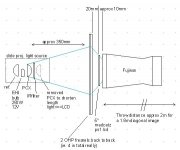
The problem is that the image brightness and quality seems to be reduced using this setup probably because of the very sharp angle of light through the lcd. Ideally light should be parallel when passing through the lcd. So the setup I had in mind was:
Attachments
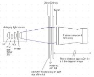
Hi Muzzman,
Cool idea. With this arrangement, you could either follow Xblocker's advice, and find a replacement input lens for your Fujinon (The fresnel might itself be the one), or, you could put a diverging lens (PCV), with the same focal length as the fresnel, flush with the input to the Fujinon.
In this arrangement, the fresnel would have reduced the diameter of the output beam from the LCD to something the Fujinon could use. A diverging lens that balanced this would then straighten out the cone at the propriate diameter for the Fujinon, AND move the virtual image forward towards the Fujinon. (The fresnel would move the virtual image of the LCD away from the Fujinon.)
Bill.
- Status
- Not open for further replies.
- Home
- General Interest
- Everything Else
- The Moving Image
- DIY Projectors
- DIY Small Panel Projector