seems quite well triggering. any schematic?
Hi Andrewlebon,
Good to see it is working.
I saw the code from ratmayor and i will test it too.
Regards and best wishes
Ronaldo
Good to see it is working.
I saw the code from ratmayor and i will test it too.
Regards and best wishes
Ronaldo
Last edited:
I'm really glad you guys brought this subject up. I recently bought a speaker protection circuit from ebay...
Check the input resistors for different values, please. 10 kOhm and 100 kOhm must be an error.
I checked. They are both 10K.
I am not sure if this discussion was ever resolved back in 2014, but I think I have figured out why the two resistor values are different:
If one of the two channels goes to either supply line, it does not really matter if the resistor is 10k or 100K, the protection circuit would surely trig.
However, if one channel goes to the positive rail and the other goes to the negative rail, (could happen if the amplifier is used in bridged mode) then if both resistors are equal the sensed error voltage might be very close to 0V, and the protection circuit might not trig. At 100k + 10K the offset voltage would still be huge, and the protection would definitely trig.
Ofcourse one could conjure up a situation where one channel would have say 4v offset, and the other -40V ( in case of a +/-40V supply), but that situation is highly unlikely to happen, and definitely more unlikely than +40V and -40V.
The optimal protection circuit will ofcourse have separate DC-sensors for each channel, but this trick will save you two transistors, two resistors and two caps.
Tell me what you think 😀
Attachments
Yes, this was commented on some years ago, but no one seems to read and they still usually make the two channels identical. That carries the small risk of no triggering.I am not sure if this discussion was ever resolved back in 2014, but I think I have figured out why the two resistor values are different:
If one of the two channels goes to either supply line, it does not really matter if the resistor is 10k or 100K, the protection circuit would surely trig.
However, if one channel goes to the positive rail and the other goes to the negative rail, (could happen if the amplifier is used in bridged mode) then if both resistors are equal the sensed error voltage might be very close to 0V, and the protection circuit might not trig. At 100k + 10K the offset voltage would still be huge, and the protection would definitely trig.
Ofcourse one could conjure up a situation where one channel would have say 4v offset, and the other -40V ( in case of a +/-40V supply), but that situation is highly unlikely to happen, and definitely more unlikely than +40V and -40V.
The optimal protection circuit will ofcourse have separate DC-sensors for each channel, but this trick will save you two transistors, two resistors and two caps.
Tell me what you think 😀
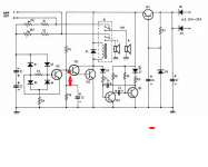

just an idea for overload protection😉
something wrong in circuit...????
with zener diode no gnd used and speaker ac voltage cannot used with zener diode.
just suggestion
just an idea for overload protection😉
greetings
this short circuit working at low level volume with adjustable pre set
thanks andrewlebon
Can anyone explain what the disadvantages would be of a simple over-current thyristor crowbar + fuse protection circuit? I've used these in the past, and they seem pretty reliable. A fuse is perhaps the ultimate latch-off arrangement!
Fuses in series with the loudspeaker have been shown to introduce distortion. If you must use them you can put them in the positive and negative DC supply lines. Then you can use a lower value and not have the distortion problem.
My preferred solution is to (latch) disconnect the DC power.
My preferred solution is to (latch) disconnect the DC power.
"Fuses in series with the loudspeaker have been shown to introduce distortion. If you must use them you can put them in the positive and negative DC supply lines. Then you can use a lower value and not have the distortion problem.
My preferred solution is to (latch) disconnect the DC power."
Yes that's what I meant - fuse in +DC line after power supply caps, followed by SCR to ground - SCR fires, sinks + volts to ground within microseconds, blows dc fuse and kills SCR current within milliseconds. Isn't that simple, cheap and effective?
Hello greetings
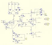
is it possible to add a latch circuit after the red point marked on
schematic relay delay on with latch scr one all ideas are
welcome
warm regards\
Andrew😉
yes, and you can use a small signal scr in place of the sensor trannie TR1.
i have used this circuit in many of my builds, they do work..
]"...............you can put them in the positive and negative DC supply lines. Then you can use a lower value and not have the distortion problem.
My preferred solution is to (latch) disconnect the DC power."
an SCR or triac across the output lines shorts the PSU charge through the amplifier's output stage.Yes that's what I meant - fuse in +DC line after power supply caps, followed by SCR to ground - SCR fires, sinks + volts to ground within microseconds, blows dc fuse and kills SCR current within milliseconds. Isn't that simple, cheap and effective?.................
Fuses usually survive longer than the output stage. What you end up with is a blown up output stage and then the fuse ruptures.
Assuming the fuse is small enough to rupture at all.
Thanks Andrew, but I didn't mean an SCR across the amplifier output, but an SCR across the power supply - so a fuse in the V+ line from the smoothing capacitor followed by an SCR to ground between fuse and regulator - SCR triggered by an overvoltage and/or overcurrent sensor, thus sinking all power and blowing fuse. Does that make sense? Could the SCR be relied on to win any "race to destruction" with other semiconductors?
Thanks Andrew, but I didn't mean an SCR across the amplifier output, but an SCR across the power supply - so a fuse in the V+ line from the smoothing capacitor followed by an SCR to ground between fuse and regulator - SCR triggered by an overvoltage and/or overcurrent sensor, thus sinking all power and blowing fuse. Does that make sense? Could the SCR be relied on to win any "race to destruction" with other semiconductors?
It was done by Mackie in the first series of the famous M1400. 2 SCRs are kill the 10A fuses, in case of output DC.
Sajti
- Home
- Amplifiers
- Solid State
- diy short circuit protection