One of these days I'm just going to put it on a DVD and toss it out, probably after I lose my mind.
Another language barrier for me. Is this mean you will do it or you will not do it?
If it is positive answer (will do it), please include me in the list, Mr. Pass 😀. I will pay for the DVD and shipment.
Hi, Jacco,
Yes, bunch of Nelson Pass articles which can be downloaded from internet has already forming a book
But I'm expecting to see cct's/articles that NP has never made public yet. I'm sure there are alot of it
I see those cct's/articles quite different than handbooks like DougSelf or RandySlone. Books like Dougself is a guidance for making audio amplifier. Mr. Pass' schematics is a guidance for making "good sounding" audio amplifier. Even it is in a form of a schematic without any word at all. 😀
What can you say. A picture (cct) equals thousands of words.
Currently, I am still exploring minimalism
Once I read that some of people sending NP better caps or accesories, and he wrote that he would appreciate more if someone is sending more linear device.
At the time I read that post, I dont take it seriously, at that time I take a transistor as it is, a perfect device.
Now somehow my search for ideal amp is stuck with transistor nonlinearities.
I read about the background of F series amp. Why make 300W power amp if 299W is not good?
So, why make 10 or 20 transistor power amp if each is producing more nonlinearities/IM?
But for now, I haven't reach the Zen era. I'm still enjoying the Threshold/Smartbias/Efficient classA era. Still a lot more interesting stuff this era.
lumanauw said:
But for now, I haven't reach the Zen era. I'm still enjoying the Threshold/Smartbias/Efficient classA era. Still a lot more interesting stuff this era.
lumanauw, you can say Nelson has been ENLIGHTENED for more than 10(?) years now.
I think more than 20 years ago he has already know what elements are tobe considered in making good sounding amps.
And what is amazing, in that era there is no internet, no handbook, no discussion forum (like we can access easily today). Achieve all that by himself.
And what is amazing, in that era there is no internet, no handbook, no discussion forum (like we can access easily today). Achieve all that by himself.
output impedance calculation
Hi Mr. Pass,
For 0.91V and 0.45V, I got Rs of 9.89ohms and 57.44ohms, but for 0.091V and 0.041V I got 998.9ohms and 997.4ohms. This two results are not the same although the ratio are. I'm confuse. Pls enlighten me on this.
Thanks.
😕
Hi Mr. Pass,
For 0.91V and 0.45V, I got Rs of 9.89ohms and 57.44ohms, but for 0.091V and 0.041V I got 998.9ohms and 997.4ohms. This two results are not the same although the ratio are. I'm confuse. Pls enlighten me on this.
Thanks.
😕
Ipanema said
Here is a Thevenin version.
The Norton version with current source and shunt resistor
gives the same answer.
I think I got the equations and numbers correct.
Tom
I'm confuse. Pls enlighten me on this.
Here is a Thevenin version.
The Norton version with current source and shunt resistor
gives the same answer.
I think I got the equations and numbers correct.
Tom
Attachments
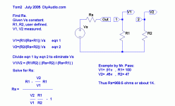
I agree with Tom2's solution. Equations 1 and 2 were derived using the Voltage Divider formula based on the attached equivalent circuit. The combined equations will also yield:
Rs=(R1R2(V1-V2))/(V2R1-V1R2)=969.5 ohms
Rs=(R1R2(V1-V2))/(V2R1-V1R2)=969.5 ohms
Nelson Pass said:The ratio is all that matters.
The way i read 0.91V is 0.91*Vs, not 0.91 volts.
solve:
0.91*X= 100/(Rs+100)
0.45*X= 47/(Rs+47)
jacco vermeulen said:
The way i read 0.91V is 0.91*Vs, not 0.91 volts.
solve:
0.91*X= 100/(Rs+100)
0.45*X= 47/(Rs+47)
Jacco, it's more like 0.91=Vs*(100/(Rs+100)) Eq1 and
0.45=Vs*(47/(Rs+47)) Eq2. (as per Voltage Divider)
Dividing Eq1 by Eq2 as Tom2 said will cancel Vs and NP's ratios remain.
The dog days of summer are nearly over.
Something must be brewing here or on passdiy for the fall!
Something must be brewing here or on passdiy for the fall!
Yes, we ran out of little paper umbrellas for our drinks on the
beach, so now it's back to work.
😎
beach, so now it's back to work.
😎
dqswim said:The dog days of summer are nearly over.B]
"Today, dog days occur during the period between July 3 and August 11."
"In the summer, however, Sirius, the “dog star,” rises and sets with the sun. During late July Sirius is in conjunction with the sun, and the ancients believed that its heat added to the heat of the sun, creating a stretch of hot and sultry weather. They named this period of time, from 20 days before the conjunction to 20 days after, “dog days” after the dog star."
Silly me, I thought it meant the hot, humid, windless days near the end of summer.
Cal
Thanks for the good reading, i like the zen variation 8 and the PLH amplifier now posted on passdiy.
That will give me something to do at work today. 😉
That will give me something to do at work today. 😉
Originally posted by Variac some time ago
I told Kent of a story I heard, that during lunch some grad students hung a piece of aluminum foil in the gap of the magnet and sent a signal through it. Of COURSE the sound was to die for.. I don't know if the actual layout of a cyclotron would allow this...
This is the traditional origin anecdote for [true] ribbon speakers. It's been so many decades that I can't remember which Chicago-area lab it was supposed to have happened at when I first heard it, or just which piece of HE physics gear was reputed to have provided the physically large gap with intense, linear magnetic field. I imagine those details change from telling to telling.
Ten to one it's apocryphal...but I do know some HE physics sorts who are pretty deeply into good sound reproduction, so I won't say it's impossible. Hmmm. I wonder if Dan is still working at Fermi...
When I was at ESS I experimented with an actual tweeter
which operated on a similar principle. A circular lightweight
foil diaphragm is placed between two coils, one front and one
back, all aligned to the same plane. When you run current
through the coils and modulate it, the eddy currents in the
diaphragm cause it to push air. The concept came from an
old acoustics journal, and I simply implemented the original
drawings. I also tried iron oxide coated mylar sheet as a
diaphragm.
As a loudspeaker, it was not a practical item.
😎
The eddy current driver sounds as though it would be inefficient. On the other hand, it might be just the ticket for a CCS amp.
Assuming that iron oxide coated mylar means magnetic recording tape, I have experimented with this with fair results. It's inefficient. Conceptually, I think it's likely that the iron oxide will experience a hysteresis effect, which would surely lead to distortion, but I don't remember it being audible.
Grey
Speaking of inefficient, I'm still waiting for Nelson to develop an efficient version of the speakers he had at CES over 20 years ago.... the ones that used the air between the grids as a diaphragm.... he's had plenty of time now!
He-he-heee....
He-he-heee....
That's not all that difficult...raise the voltage. But it will also become a more efficient source of ozone in the process.
Grey
(Nix Fingerpokin, indeed...more like Nix Inhalin')
Grey
(Nix Fingerpokin, indeed...more like Nix Inhalin')
New Line Stage?
Any chance of a new line stage that uses the power JFETS?
Would the power JFET be an improvement over the MOSFETS used in
the BZLS?
Or am i asking a really stupid question! LOL 🙂
Any chance of a new line stage that uses the power JFETS?
Would the power JFET be an improvement over the MOSFETS used in
the BZLS?
Or am i asking a really stupid question! LOL 🙂
- Home
- Amplifiers
- Pass Labs
- DIY progress report